The test is made by means of injection of voltage and current where the amplitude of both
current and voltage and the phase angle between the voltage and current can be controlled.
During the test, the analog outputs of active and reactive power shall be monitored.
1. Connect the test set for injection of voltage and current corresponding to the mode
to be used in the application. If a three-phase test set is available this could be used
for all the modes. If a single-phase current/voltage test set is available the test set
should be connected to a selected input for one-phase current and voltage.
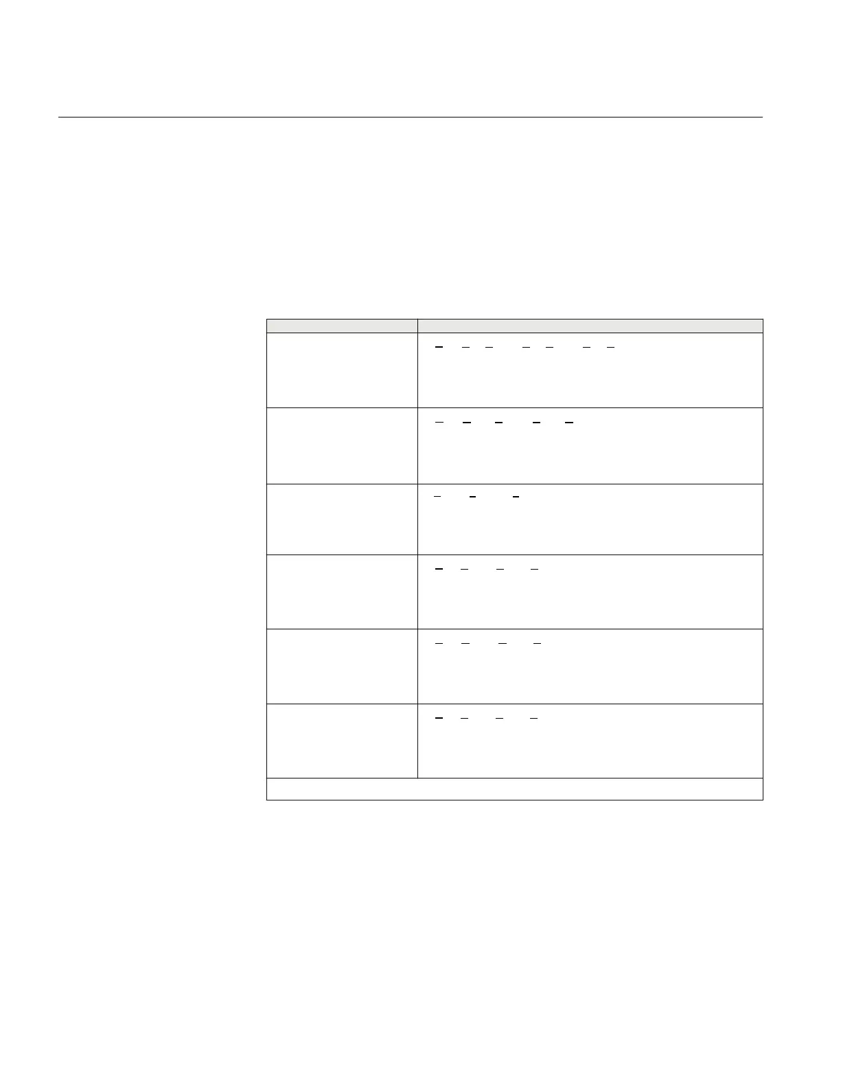
Table 33: Calculation modes
Set value:
Mode
Formula used for complex power calculation
A, B, C
* * *
A A B B C C
S V I V I V I= × + × + ×
EQUATION2055 V1 EN (Equation 80)
Arone
* *
AB A BC C
S V I V I= × - ×
EQUATION2056-ANSI V1 EN (Equation 81)
PosSeq
*
3
PosSeq PosSeq
S V I= × ×
EQUATION2057-ANSI V1 EN (Equation 82)
AB
EQUATION2058-ANSI V1 EN (Equation 83)
BC
EQUATION2059-ANSI V1 EN (Equation 84)
CA
EQUATION2060-ANSI V1 EN (Equation 85)
Table continues on next page
Section 11 1MRK 504 165-UUS -
Testing functionality by secondary injection
198 Transformer protection RET670 2.2 ANSI
Commissioning manual

 Loading...


