If the function LDC is set to Zero, this test is omitted.
2. Open the voltage control display on the LHMI in Main Menu/Control/
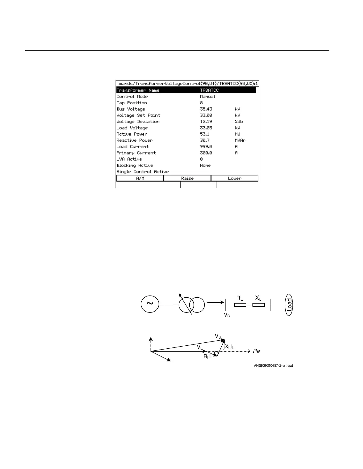
Commands/TransformerVoltageControl (ATCC, 90).
3. In this view, check the following settings:
3.1. Check that Control Mode is set to Manual.
3.2. Operate the tap changer so that the Load Voltage corresponds to the Voltage
Set Point.
3.3. Check that neither the Raise or the Lower command are operating. Voltage
Deviation should be less than 100%.
3.4. Compare the values of Bus Voltage and Load Voltage.
UL can be obtained by a vector calculation where IL is the load current and
values for RL and XL are the settings given in primary system ohms.
~
Load
R
L
X
L
V
B
V
L
V
B
R
L
I
L
jX
L
I
L
Re
ANSI06000487-2-en.vsd
For inductive load, the Bus Voltage should be higher than the Load Voltage. If not, current
circuits are incorrect and must be reversed. Incorrect current polarity may be an issue with
Section 12 1MRK 504 165-UUS -
Primary injection testing
288 Transformer protection RET670 2.2 ANSI
Commissioning manual

 Loading...


