Settings/General settings/Control/TransformerVoltageControl(ATCC,90)/
TR8ATCC:x/ParCtrl/CircCurrLimit.
3. Connect all transformers in the parallel group to the same busbar on the secondary
side.
4. Open the test display for Transformer Voltage Control on the LHMI in Main menu/
Test/Function status/Control/TransformerVoltageControl(ATCC,90).
5. Manually execute Raise commands to step up the tap changer for transformer T1 to
two steps above the setting for the other transformers in the parallel group.
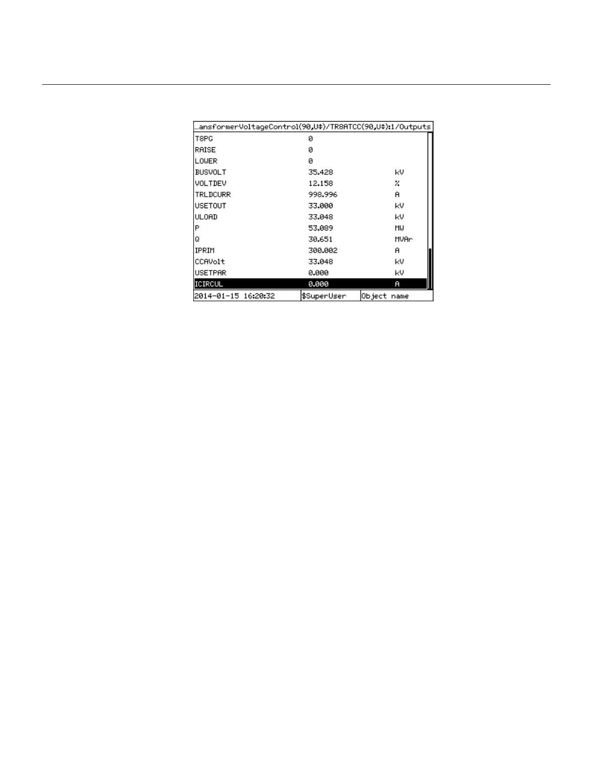
6. Check that the value of IPRIM is below the overcurrent blocking level (Iblock)
7. Check that the value of ICIRCUL is below the circulating current limit
(CircCurLimit).
8. Set the control mode to Automatic for all transformers.
9. For transformer T1, adjust the parameter Comp on the local HMI in Main menu/
Settings/Setting group N/Control/TransformerVoltageControl(ATCC,90)/
TR8ATCC:x/ParCtrl/Compso that the LOWER output is activated due to
circulating current.
Comp is a setting for circulating current Compensating Factor, and it is effectively
a multiplier value to change the sensitivity of the voltage regulation function to
measured values of circulating current. A nominal value of 200 for Comp should be
appropriate to achieve sensitive voltage regulation. Smaller values may lead to a
normal state where tap changers for parallel transformers are well out of step, and
values significantly higher will cause over-sensitivity in the voltage control function
and tap changer hunting behavior. It is an important outcome of the testing process
that the compensating factor is checked for each transformer to ensure sensitive but
stable operation for circulating currents.
For example, if there are three transformers connected in parallel, and the tap
changer of transformer T1 is two steps over the tap changer of T2 and T3, the
circulating current detected by the VCTR for T1 will be the sum (with opposite sign)
of the current measured at T2 and T3. The currents measured at T2 and T3 will
ideally be about the same values. If the voltage is close to the upper limit of the
Section 12 1MRK 504 165-UUS -
Primary injection testing
290 Transformer protection RET670 2.2 ANSI
Commissioning manual

 Loading...


