XIO USER MANUAL | 2106424MNAA | 29
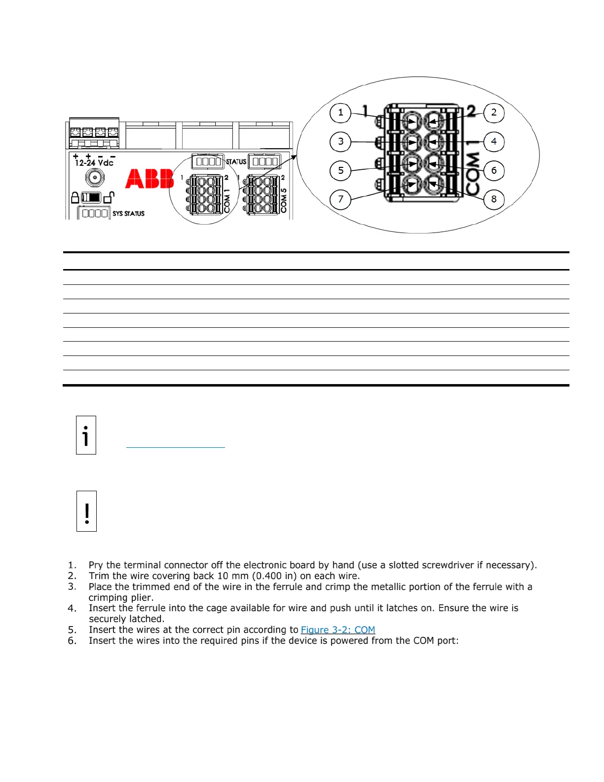
Figure 3-2: COM 1 to COM 8 serial communication port pinouts
Legend: COM 1 to COM 8 serial communication port pinouts
Switched voltage (SW VOUT)
Switched voltage (SW VOUT)
Switched voltage (SW VOUT)
To wire the serial communication port:
: XIO user drawings provide COM wiring details for specific external devices. See
Additional information section.
– Equipment damage. Pin 1 (VOUT) or pin 3 (SW VOUT) can power an external device on
all COM ports. The external power supply connected to the
power port determines the output voltage
Verify that the device is compatible with the input voltage at the
power port before connecting to
these pins. Connection to an incompatible device can result in damage to the device.
• Use pin 1 (VOUT) and pin 2 (GND) to provide constant voltage.
• Use pin 3 (SW VOUT) and pin 2 (GND) to provide switched voltage.