AcerPower 6000 User’s Guide2-8
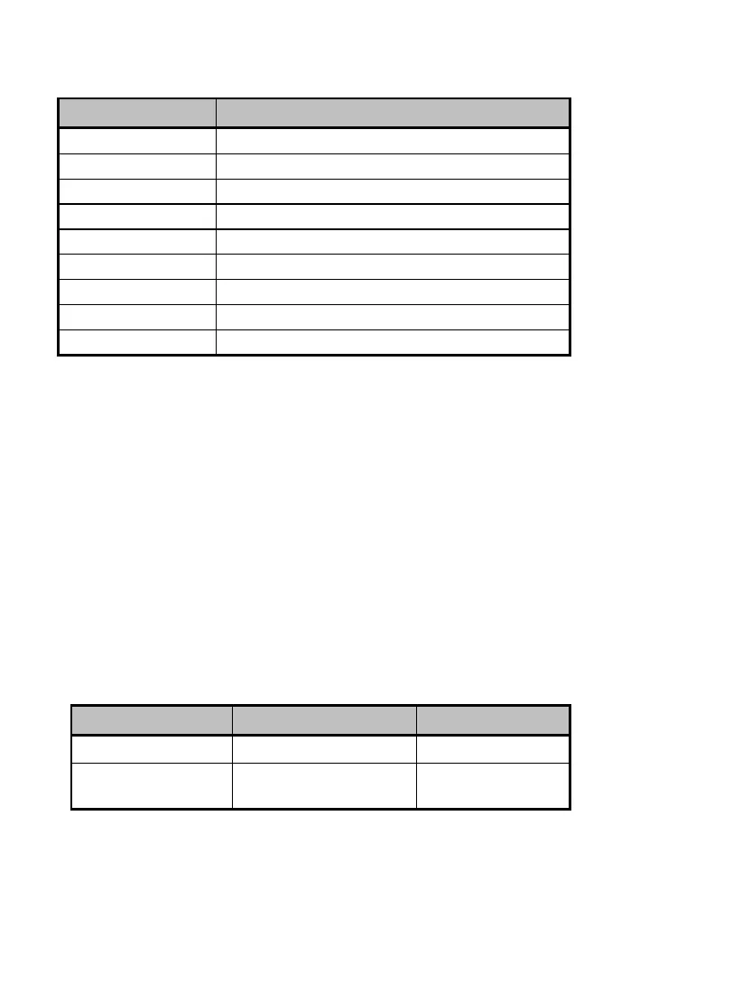
Table 2-2 Onboard Connectors (continued)
Connector Function
CN16 Wake-on LAN connector
CN17 Modem ring-in connector
CN18 HDD LED/message in connector
CN20 Audio connector
CN21 Turbo/LAN LED connector
CN22 3-pin power connector
FN1 3-pin fan connector
FN2 2-pin fan connector
JP2401 Thermal sensor connector
2.4 IDE Hard Disk Support
The board comes with an enhanced PCI IDE controller that supports PIO mode 4
and Ultra DMA (Direct Memory Access) mode data transfers. In addition, two PCI
IDE interfaces are mounted on the riser card to enable the system to support a
maximum of four IDE hard disks, or any other IDE devices. See Figure 2-2 for the
location of the IDE interfaces.
Connect the cables according to the IDE hard disk configuration in Table 2-3.
Follow the instructions in the housing installation manual on how to install a hard
disk in the system.
Table 2-3 IDE Hard Disk Configuration
IDE Connector Master Slave
IDE1 (CN5) Hard disk 0 Hard disk 1
IDE2 (CN6) Hard disk 2/
IDE CD-ROM drive
Hard disk 3