3-28 Machine Maintenance Procedures
Palmrest Assembly Installation 0
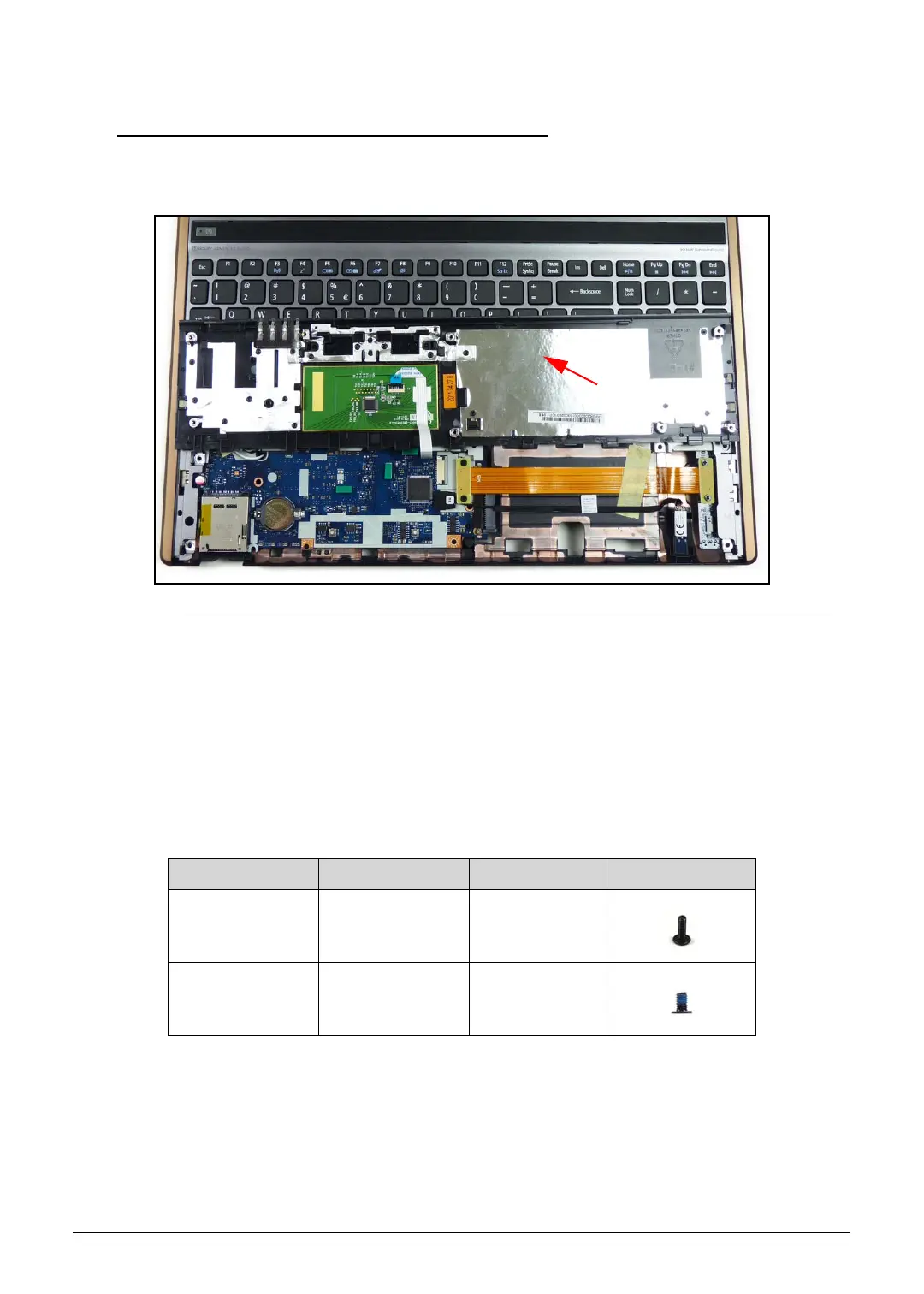
1. Align palmrest assembly (E) with the keyboard as shown in Figure 3-27.
Figure 3-27. Palmrest Assembly
2. Connect touchpad FFC (C) to touchpad module connector (D) (Figure 3-26).
3. Put palmrest onto lower cover. (Figure 3-25)
4. Install and secure two (2) screws (B) to lower cover. (Figure 3-23)
5. Install and secure six (6) screws (A) to lower cover. (Figure 3-22)
6. Install HDD module.
7. Install base door.
ID Size Quantity Screw Type
A M2.45x8.0 8
B M2.5x5.0 2
SG_JV51_HR.book Page 28 Friday, July 8, 2011 5:58 PM

 Loading...