3-32 Machine Maintenance Procedures
Upper Cover Installation 0
1. Align upper cover to lower cover. Make sure keyboard FPC (E) is visible. (Figure 3-32)
2. Connect keyboard FPC (E) to mainboard connector (G). (Figure 3-32)
3. Connect power board FFC (F) to mainboard connector (H). (Figure 3-32)
4. Secure lower cover latches to upper cover.
5. Install and secure screw (C) to upper cover (Figure 3-30).
6. Place computer facedown.
7. Install and secure five (5) screws (B) to lower cover battery bay. (Figure 3-29)
8. Install and secure eight (10) screws (A) to upper cover (Figure 3-28).
9. Install palmrest assembly.
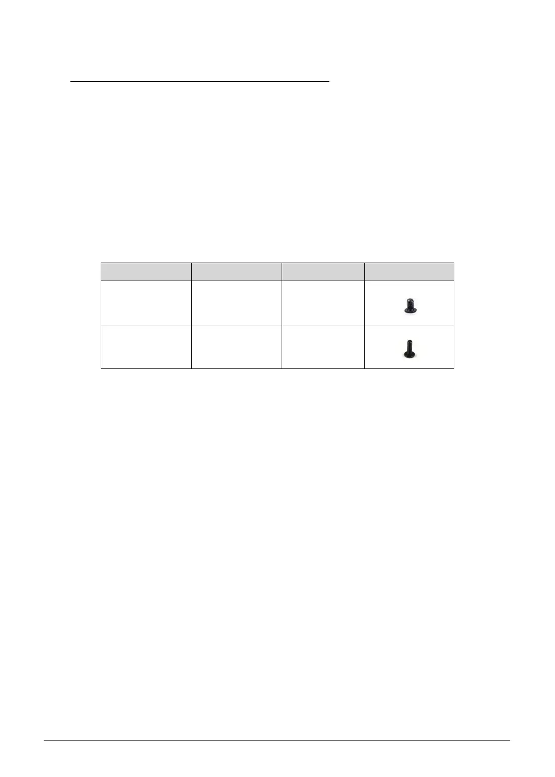
ID Size Quantity Screw Type
B M2.0x3.0 5
A,C M2.45x8.0 11
SG_JV51_HR.book Page 32 Friday, July 8, 2011 5:58 PM

 Loading...