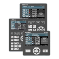
12.3 MIC 3000
See data sheet: Process controller MIC 3000 » universal cooking and smoking chambers as well as
climatic smoke and maturing chambers.
http://www.aditec.net/MIC3000_data-sheet_en.pdf
13 Index
A
actual values ................................................ 8, 18
Alarm signal ..................................................... 34
B
Batch number .................................................. 33
C
chamber temperature ...................... 7, 24, 32, 47
Cleaning ........................................................... 52
configuration ........................................ 16, 19, 46
Connection diagram ....................... 47, 48, 49, 50
core shut-down .......................................... 32, 47
D
Delta temperature ...................................... 16, 24
Delta value ................................................... 8, 24
F
Favourites .................................................. 13, 18
FC value......................................... 16, 32, 33, 47
H
housing .................................................. 5, 52, 53
humidity...................... 7, 8, 15, 32, 35, 46, 47, 52
I
Installation instructions .................................... 52
L
Linking.................................................. 26, 27, 47
List of errors ..................................................... 46
M
maintenance .................................................... 20
O
Operating mode ............................................... 31
P
Power failure .................................................... 46
profiles ............................................................. 19
program selection ................................ 20, 21, 22
Program start ................................................... 28
Programming mode ......................................... 21
R
Relay outputs ................................................... 52
repetitive steps .......................................... 22, 24
S
safety instructions ............................................ 52
screensaver ............................................... 45, 46
sensor break .............................................. 34, 46
Sensor leads .................................................... 52
sensor short circuit .......................................... 46
Shut-down conditions ...................................... 32
signal ......................................................... 39, 52
Single step control ..................................... 34, 47
source voltage ................................................. 52
standby page ............................................. 22, 33
start time ...................................................... 7, 28
Start with time of day ....................................... 28
step combinations............................................ 24
Symbols ....................................................... 4, 12
T
task bar .. 7, 14, 19, 21, 22, 24, 25, 28, 31, 34, 37
Technical data ................................................. 50
V
Ventilation ........................................................ 52
Version ...................................... 5, 21, 28, 36, 41
W
Waiting mode ................................................... 28
Waiting time ............................................... 28, 46