Total Access
®
3000/3010 System Manual
6TAATP602-1E
TOTAL ACCESS 3000/3010
ATP-602
Page 2 of 6
© 2002, ADTRAN, Inc.
1.2 Acceptance Test Procedure ATP-602
1. Verify LED Operation
Verify operation of faceplate LEDs by pressing the Test/Enable button. LEDs
should illuminate while button is pressed.
2. Verify BNC Connector Installation
Use the procedure outlined in DLP-708 to verify the installation of the BNC
module connector to the Total Access 3000/3010 shelf backplane. If an installation
problem is found, correct the problem before proceeding.
For details, go to: DLP-708.
3. Verify Coaxial Cable Installation
Use the procedure outlined in DLP-709 to verify the installation of the coaxial
cable and its connection to the BNC module. If a problem is found with the
installation or connection, correct the problem before proceeding.
For details, go to: DLP-709.
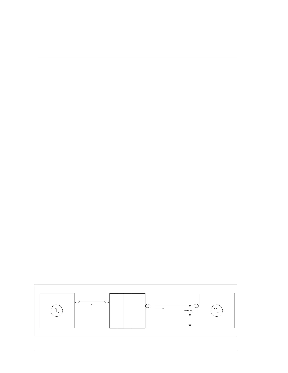
4. Pulse Shape Measurement
Use an oscilloscope and the diagram below to verify the pulse shape produced by
the module.
A. Set up measuring circuit as shown in Figure 1.
B. Set up the pattern generator for an Isolated Ones Pattern (001).
C. Set the DS-3 line buildout for appropriate line length.
Use an oscilloscope and the diagram below to verify the pulse shape
produced by the module.
D. Set the DS-3 Network Loopback to “Looped.”
E. Verify the pulse shape of the DS-3 output signal is within the specified
waveform mask in Figure 2.
5. Power Level Test
A. Connect the test circuit shown in Figure 3.
B. Set the LBO to “Long” in the DS-3’s Provisioning Menu.
Figure 1. Pulse Shape Measurement
Oscilloscope
TX
TDS 754A
(225 or 450 ft.)
75Ω
+/- 5%
Total Access 3000/3010
WECO 728A
or
Equivalent
WECO 728A
or
Equivalent
DS-3 Pattern Generator
RXTX
TTC-310