Total Access
®
3000/3010 System Manual
6TADLP702-1E
TOTAL ACCESS 3000/3010
DLP-702
Page 2 of 4
© 2002, ADTRAN, Inc.
Perform Steps Below in the Order Listed
1.2 Detailed Level Procedure 702
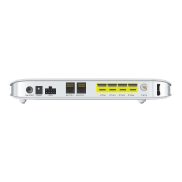
1.2.1 Connect a Composite Clock to a Total Access 3000/3010 Shelf
1. Locate Clock wiring
Determine the “+” (or T), “–” (or R), and drain or ground wires from the CO clock
source.
2. Strip the Ends of the Clock Wire for Wire-Wrapping
Using wire strippers, strip 1 inch to 1-1/2 inches of the insulation from the end of
the clock source twisted pair, shielded, drop wire.
3. Connect the “+” Lead
Using a wire wrap tool, wire wrap the “+” or T terminal from the clock source to
the pin marked “+” on connector P4/P10, “EXTCLK A-IN.”
4. Connect the “–” Lead
Using a wire-wrap tool, wire wrap the “-” or R terminal from the clock source to
the pin marked “-” on connector P4/P10, “EXTCLK A-IN.”
5. Terminate the Shield Drain Wire
Wire wrap the drain or shield pin from the clock source to the pin marked “S” on
connector P4/P10, “EXTCLK A-IN,” if required.
6. Dress Out the Wiring
Tie the clock source wire neatly to the frame.
7. Set Termination Mode
On the daughter card mounted to the left of, and slightly below, P4/P10, move the
jumper so that the left two pins, labeled “TERM IN,” are connected together.
Up to eight Total Access 3000/3010 shelves may be daisy chained to a single output
from the timing source, so only one wire run is required from the timing source for an
installation of up to eight Total Access 3000/3010 shelves. Use wire of the same type
as was used for the wire run from the CO clock source to the Total Access 3000/3010
shelf.