240 Programmed Temperature Vaporization Inlet (PTV)
Solvent vent mode
12 of 46
Jun 2001
Inlets
Agilent 6890 Gas Chromatograph Service Manual
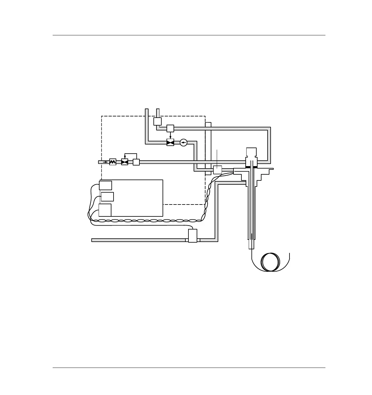
Stage 3: Purge and cleanup
The solenoid valve opens again and the system returns to the Stage 1
configuration but with different setpoints. The PTV inlet is flushed through
the split vent.
Figure 240-6 Solvent vent mode flow control diagram: purge and cleanup
Split
vent
SPR
vent
Septum
holder
To de te c t or
Flow
limiting
frit
Tota l flo w
control loop
PS
SPR
PV1
PV2
FS
Cryo
valve
PTV thermocouple PCB
Tr a p
Valve
open
 Loading...


