1 of 14
Jun 2001
Cabling Configuration and Electronics
Agilent 6890 Gas Chromatograph Service Manual
1010 Cabling Diagrams, 6890A and
6890 Plus
Overview of 6890 GC cable connections
There are numerous system configurations available with the 6890 GC, and
your cabling requirements will be determined by the system’s components.
In the figures that follow, refer to the configuration most closely resembling
your system.
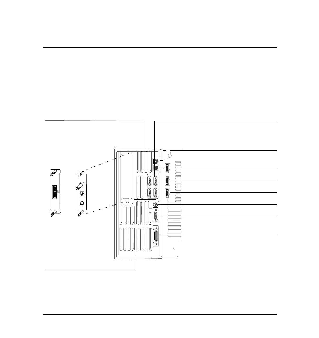
Figure 1010-1 Connectors on the back of the GC
OR
Analog output for integrators or analog
RS-232 for modem or non-Agilent
External event for communication with
BCD input for stream selection valves
General Purpose Interface Bus (GPIB) for
ChemStation
INET card for
3396B/C
integrators
LAN card for
a networked
Chemserver
Power and communication for front
G2613A Injector
Power and communication for back
G2613A Injector
Power and communication for
to digital (A/D) converters
and some non-Agilent headspace samplers
Remote start-stop for communication with
3395/3396 integrators, GC ALS, Mass Selective
Detector, 35900 C/D/E analog/digital interface
and other GCs
RS-232 for Controller,18594 A/B or
G1512A, GC Automatic Liquid Sampler
(GC ALS)
unspecified, non-Agilent instruments
controller
G2614A tray
 Loading...


