Chapter 9 291
BERT
Bit Error Rate Tester–Option UN7
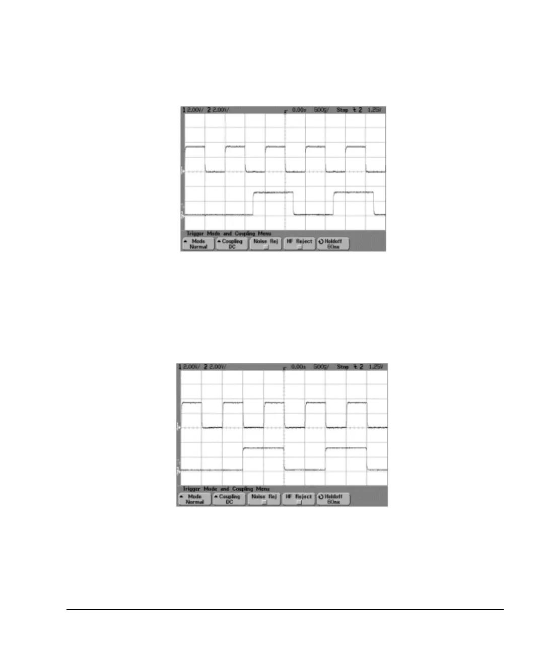
Figure 9-21
CH1: BER TEST OUT (pin 20 of AUX I/O connector)
CH2: BER MEAS END (pin 1 of AUX I/O connector)
In this example, the clock delay function is on. The rising edge of the clock was delayed by 200 ns and was
adjusted to the center of the data. Figure 9-22 indicates the result of the using the clock delay function.
Figure 9-22
CH1
CH2
CH1
CH2