546 Chapter 16
W-CDMA Uplink Digital Modulation for Receiver Test
Configuring Rear Panel Output Signals
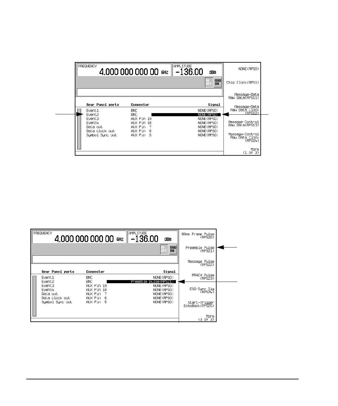
Figure 16-66 Output Connector Selection
2. Press
More (1 of 3) > More (2 of 3) > Preamble Pulse (RPS21).
Notice that under the Signal column in row two of the text display, NONE(RPSO) changed to
Preamble pulse(RPS21). This corresponds to the Event2 connector listed under the Rear Panel
ports column. Figure 16-67 shows what the ESG display looks like after the preamble pulse selection
is made.
Figure 16-67 Output Trigger Signal Selection
Event2 Connector
Selection
Highlighted
Item
Preamble Pulse
Trigger Selected
Preamble Pulse
Softkey