Troubleshooting
Getting Started with Troubleshooting
1-11
The pulse state signals listed in Table 1-6 on page 1-10 are control lines, clock, and data for the A2 Display. If
any of the above signals are bad, use Table1-7 to check them at P221 of A31 Motherboard. If the signals in
table 1-9 are good, then check the signals in Table1-8 at J9 of the A3 Power Switch. To access J9 the front
panel must be removed from the chassis frame and laid face down.
If any signals in Table1-7 are bad, replace the A18 CPU.
If the signals in Table1-8 are good, then replace A2 Display. If the signals are not good, then replace
A3 Power Switch.
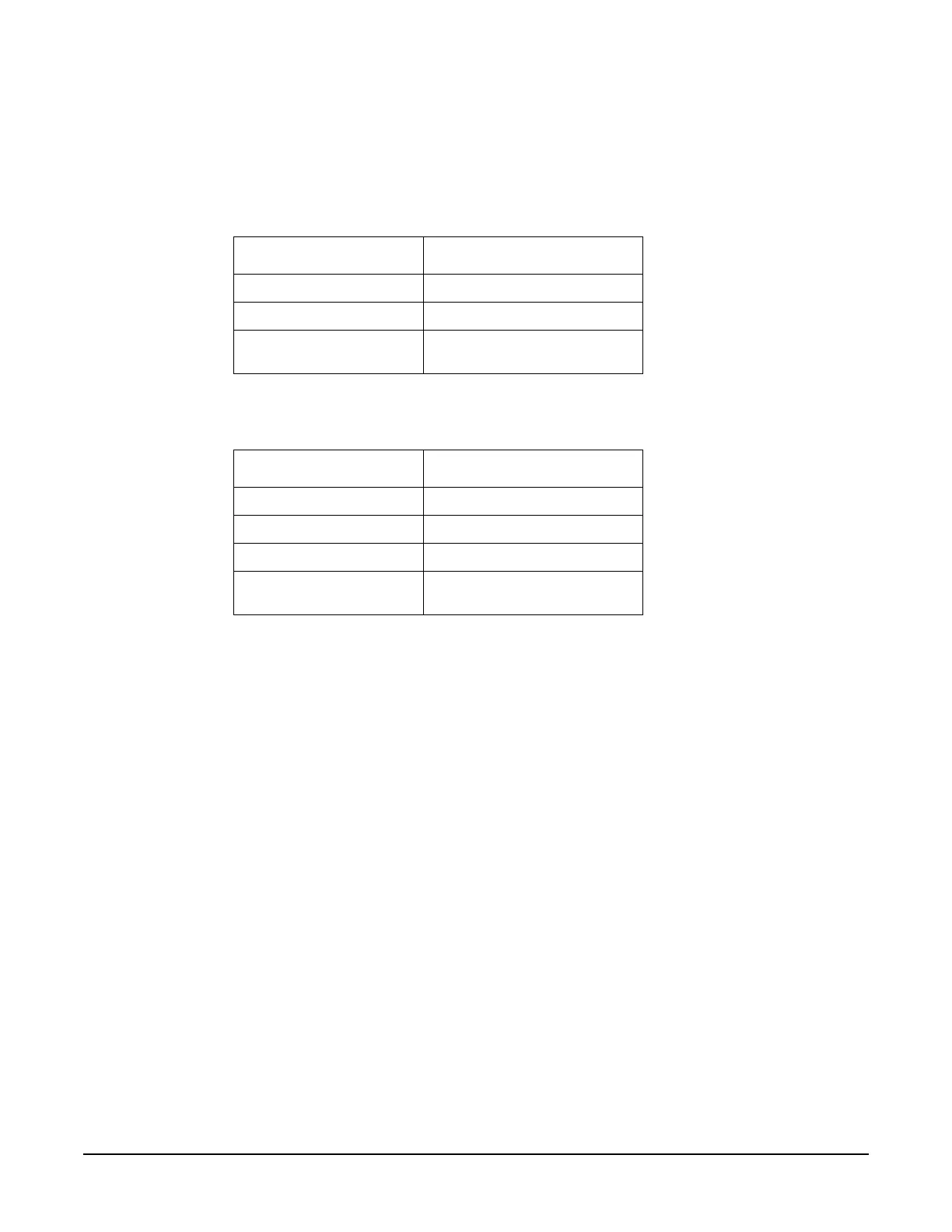
Table 1-7
Signal State
P221-14 VLCD approx. 21 Vdc
P221-53 LCD_ENABLE_H >3 Vdc
P221-1 to 13, 15, 41, 43, 45,
47, 49 to 52
Refer to Pulsing Activity in Figure
1-1 on page 10.
Table 1-8
Signal State
J9-7 VLCD approx. 21 Vdc
J9-4 LCD_ENABLE_H >3 Vdc
J9-5 5.2 Vdc
J9-1, 2, 3, 8 to 15 Refer to Pulsing Activity in Figure
1-1 on page 10.

 Loading...


