Troubleshooting
Troubleshooting Assembly Level Problems
1-30
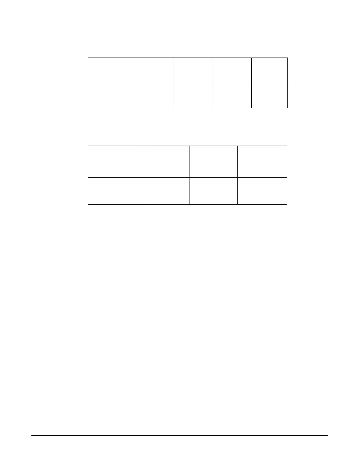
A9 YIG Driver Output Voltages
If any of the voltages in Table1-21 are out of specification, replace the A9 YIG Driver.
600 Post Regulator
1. Replace the A9 YIG Driver.
601 DACs
1. Replace the A9 YIG Driver.
602 PLL Interface
1. Remove the cable from the A5 Sampler to J4 on the A9 YIG Driver.
2. Loop self-test 602 and using an oscilloscope measure the voltage on J4. The voltage should pulse to
+10 Vdc.
3. If the voltage is +10 Vdc, replace the A9 YIG Driver.
4. If the voltage on J4 is bad, replace the A5 Sampler.
603 FM Driver
1. Remove the cable from the A6 Frac-N to J3 on the A9 YIG Driver.
2. Loop self-test 603 and using an oscilloscope measure the voltage on J3. The voltage should be
approximately -1.3 Vdc.
3. If the voltage is approximately -1.3 Vdc, replace the A9 YIG Driver.
4. The voltage on J3 originates on the A11 Pulse/Analog Modulation Generator and passes through the A6
Frac-N. If the voltage is bad at J3 check it entering the A6 Frac-N at P31-11. If the voltage is bad,
troubleshoot the A11 Pulse/Analog Modulation Generator. If the voltage is good entering the A6 Frac-N,
then troubleshoot the Frac-N.
+3.4 Digital Low P111-60, 61,
62, 63, 125,
126, 127, 128
+3.29 +3.5 Main Supply
Table 1-21
SupplyVoltage
(Vdc)
Connector
Pins
Minimum
Value (Vdc)
Maximum
Value (Vdc)
+9 P112-17, 18, 42 +8.82 +9.18
-5.2 P112-1, 2,
26, 27
-5.1 -5.3
-6 P112-19, 44 -5.88 -6.12
Table 1-20
Supply
Voltage
(Vdc)
Connector
Pins
Minimum
Value
(Vdc)
Maximum
Value
(Vdc)
Origin

 Loading...


