Troubleshooting
Troubleshooting Assembly Level Problems
1-32
701 Loop Gain
1. Replace the A6 Frac-N.
702 Tuning Voltage
1. Check 10 MHz Synthesis line on P33-15 using an oscilloscope. The signal period should be 100 ns with an
amplitude of approximately 3 V
p-p
.
2. If the signal is good, replace the A6 Frac-N.
3. If the signal is bad, turn the signal generator power off and remove the A6 Frac-N. Measure the P33-15
again.
4. If the signal is good, replace the A6 Frac-N, if the signal is still bad, measure P41-5 on the A7 Reference. If
the signal is good, at P41-5, replace the A31 Motherboard.
5. If the signal is bad on P41-5, replace the A7 Reference.
703 Output Voltage
1. Check 10 MHz Synthesis line on P33-15 using an oscilloscope. The signal period should be 100 ns with an
amplitude of approximately 3 V
p-p
.
2. If the signal is good, replace the A6 Frac-N.
3. If the signal is bad, turn the signal generator power off and remove the A6 Frac-N. Measure the P33-15
again.
4. If the signal is good, replace the A6 Frac-N, if the signal is still bad, measure P41-5 on the A7 Reference. If
the signal is good, at P41-5, replace the A31 Motherboard.
5. If the signal is bad on P41-5, replace the A7 Reference.
704 Filter Test
1. Turn the signal generator on and remove the A6 Frac-N. Set the signal generator to the first frequency in
column one in Table1-23. Use an extender board cable to connect a spectrum analyzer to J1. Tune the
spectrum analyzer to the first frequency in column two of Table1-23 and check for power > -6 dBm. Tune
the signal generator and spectrum analyzer to the next set of frequencies in the table and check for power.
Continue until all frequencies have been checked. If all the signals are good continue to step d.
2. If the signal is bad, check the signal out of the A29 20 GHz Doubler A6 Frac-N output port. If the signal
out the A29 20 GHz Doubler is good, replace the cable.
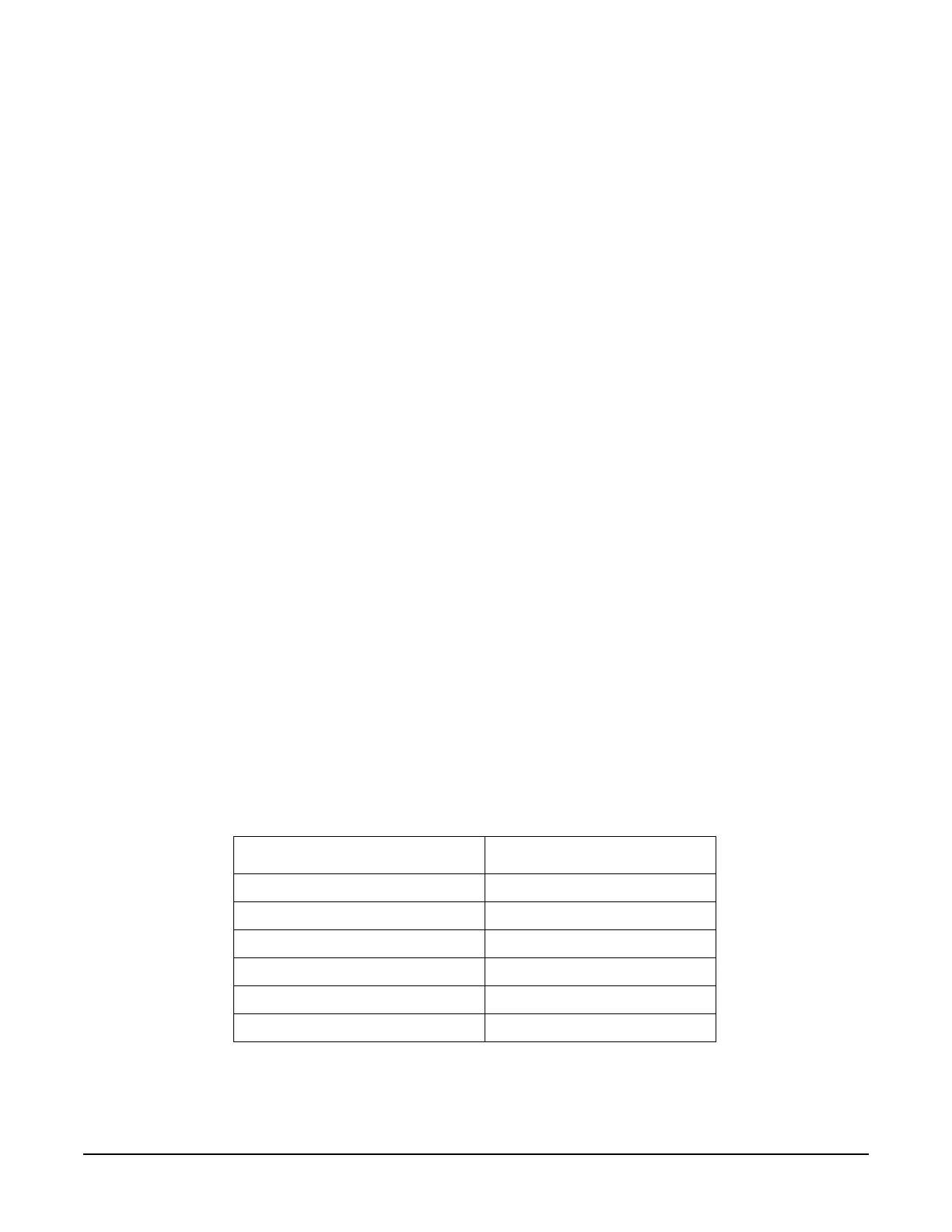
Table 1-23
Center Frequency (GHz) J1 Frequency (GHz)
.300 4.771
.500 7.969
.750 5.971
1.25 4.976
2.0 7.969
3.0 5.971

 Loading...


