Troubleshooting
Troubleshooting Unlevels
1-50
• Set Stop Frequency to 3.25 GHz
• Set Reference Level to +30 dBm
• Set Display to Max Hold
b. Connect the RF output of the signal generator to the spectrum analyzer. Measure and record the
minimum power level.
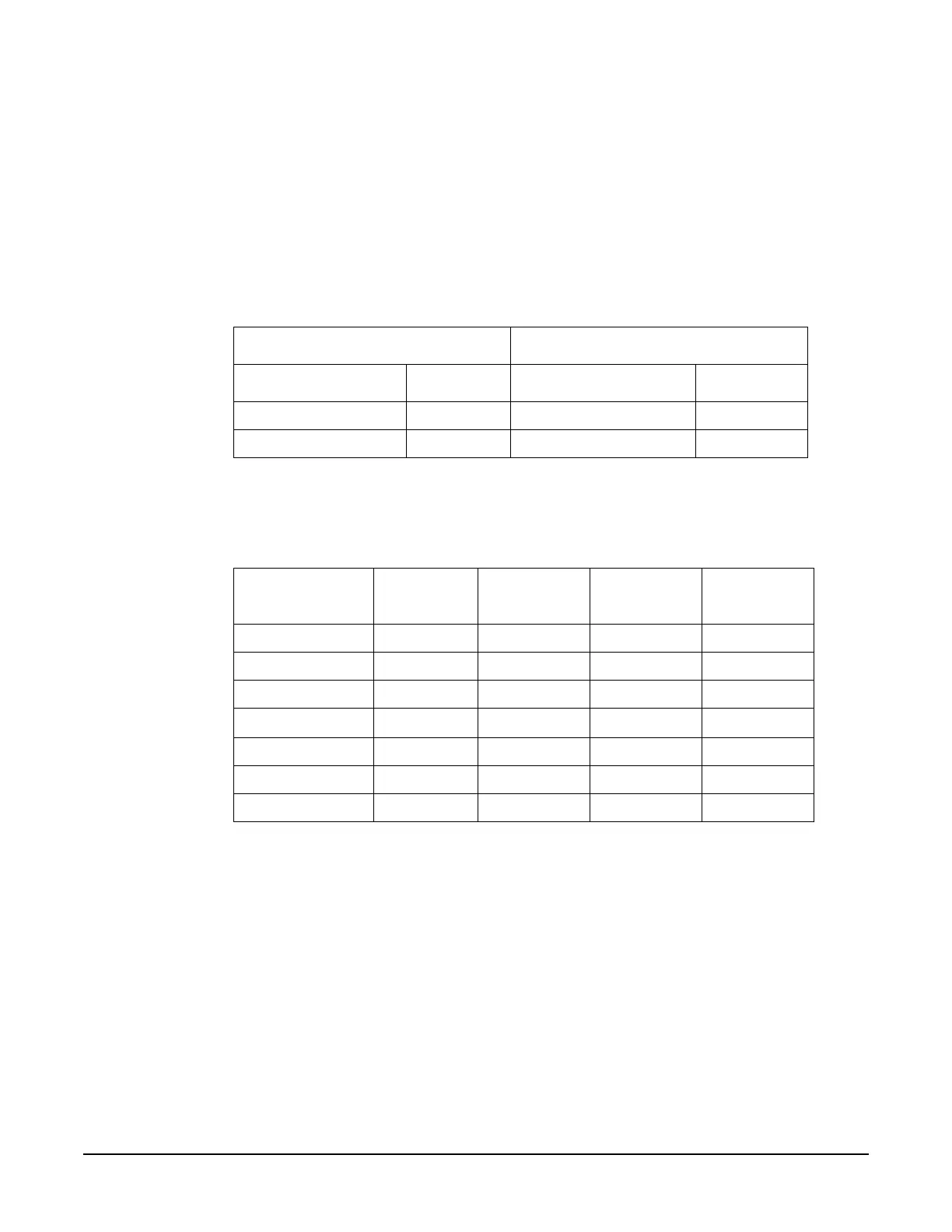
c. Set the signal generator and spectrum analyzer start/stop frequencies to the next start/stop
frequencies in Table1-32. Repeat step b above.
d. If any of the frequency ranges do not produce power levels ≥ the maximum leveled power shown in the
Table1-33, set the signal generator to the frequency with the lowest power level and measure the power
with a power meter. If the power level is low, troubleshoot the RF path before proceeding.
3. If the RF signal levels are good, most likely the problem is either a detector, ALC, or modulator. Before
proceeding, turn ALC On and set the signal generator to maximum leveled power for the model and
options you have and note the frequencies where the unleveled condition occur. Later, when
troubleshooting in ALC Off mode the unleveled indication is turned off.
Table 1-32
Signal Generator Spectrum Analyzer
Start Stop Start Stop
3.2 GHz 20 GHz 3.15 GHz 20 GHz
20 GHz 19.5 GHz 40 GHz 40 GHz
Table 1-33
20 GHz Models Standard Option 1EA Option 1E1 Option 1E1
with 1EA
250 kHz to 3.2 GHz +13 dBm +16 dBm +11 dBm +15 dBm
3.2 GHz to 20 GHz +13 dBm +20 dBm +11 dBm +18 dBm
40 GHz Models
250 kHz to 3.2 GHz +9 dBm +15 dBm +7 dBm +14 dBm
3.2 GHz to 20 GHz +9 dBm +18 dBm +7 dBm +16 dBm
20 GHz to 40 GHz +9 dBm +14 dBm +7 dBm +12 dBm

 Loading...


