Home
Agilent Technologies
Measuring Instruments
U1731C
Agilent Technologies U1731C User Manual
4
of 1
of 1 rating
107 pages
Give review
Manual
Specs
To Next Page
To Next Page
To Previous Page
To Previous Page
Loading...
3S
e
t
u
p
O
p
t
i
o
n
s
Setup Menu Items
74
U1731C/U1732C/U
1733C User’s Guide
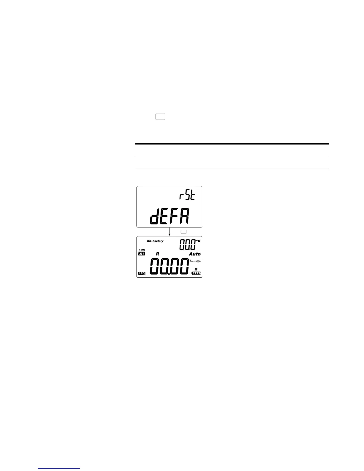
Resetting the Setup items
The Setup items can be reset t
o t
heir default values through
thi
s Se
tup it
em
.
Pr
es
s
to pe
rf
orm
the
re
se
t.
The L
CR
me
te
r w
il
l b
ee
p
once, exit the Setup menu, and return t
o normal operation.
Figure 3-16
Resetting th
e Setup items
Parameter
Range
Default setting
rSt
dEF
A
dEF
A
Rec
Hold
P
r
es
s
Rec
Hold
91
93
Table of Contents
Default Chapter
2
Restricted Rights Legend
2
Safety Symbols
3
Safety Considerations
4
Environmental Conditions
6
Table of Contents
11
1 Introduction
19
About this Manual
20
Documentation Map
20
Safety Notes
20
Preparing Your LCR Meter
21
Check the Shipment
21
Install the Battery
21
Figure 1-1 Installing the Batteries
22
Turn on Your LCR Meter
23
Figure 1-2 Power-On Button
23
Table 1-1 Battery Level Indicator
23
Automatic Power-Off (APO)
24
Enabling the Backlight
24
Selecting the Range
25
Adjusting the Tilt Stand
26
Figure 1-3 Tilt-Stand Adjustment and IR Cable Connection
26
Connecting the IR-USB Cable
27
Figure 1-4 Agilent GUI Data Logger Software
27
Power-On Options
28
Table 1-2 Power-On Options
28
Your LCR Meter in Brief
29
Dimensions
29
Figure 1-5 Width Dimensions
29
Figure 1-6 Height and Depth Dimensions
30
Overview
31
Figure 1-7 Front Panel
31
Table 1-3 Front Panel Parts
31
Figure 1-8 Rear Panel
32
Table 1-4 Rear Panel Parts
32
Keypad
33
Table 1-5 Keypad Functions
33
Display Screen
36
Table 1-6 General Annunciators
36
Table 1-7 Measurement Units Display
39
Input Terminals
40
Table 1-8 Input Terminal/Socket Connections
40
Cleaning Your LCR Meter
41
2 Features and Functions
43
Making Measurements
44
Auto Identification (Ai) Function
44
Figure 2-1 Using the Ai Function
44
Table 2-1 Auto Identification Phase Angle Rules
45
Table 2-2 Auto Identification Series/Parallel Rules for Resistance
45
Table 2-3 Auto Identification Series/Parallel Rules for Capacitance
46
Table 2-4 Auto Identification Series/Parallel Rules for Inductance
46
Measuring Inductance (L)
47
Figure 2-2 Inductance Measurement with Q Factor
47
Figure 2-3 Measuring Inductance
48
Measuring Capacitance (C)
49
Figure 2-4 Capacitance Measurement with D Factor
49
Figure 2-5 Measuring Capacitance
50
Measuring Resistance (R)
51
Figure 2-6 Resistance Measurement
51
Figure 2-7 Measuring Resistance
52
Measuring Impedance (Z)
53
Figure 2-8 Impedance Measurement with Theta
53
Figure 2-9 Measuring Impedance
54
Measuring Dissipation Factor/Quality Factor/Phase Angle (D/Q/ Θ )
55
Measuring Dissipation Factor/Quality Factor/Phase Angle (D/Q/Θ)
55
Changing the Test Frequency
55
Selecting Parallel/Series Circuit Mode (P/S)
55
Table 2-5 Available Test Frequencies
55
Setting the Standard Reference Tolerance (Tol%)
56
Figure 2-10 Component above Setting Tolerance
56
Enabling ESR Measurements
57
Enabling DCR Measurements
57
Figure 2-11 ESR Measurement with Theta
57
Figure 2-12 DCR Measurement
57
Additional Features
58
Freezing the Display (Hold)
58
Enabling the Static Recording Mode (Rec)
58
Figure 2-13 Using the Hold Function
58
Figure 2-14 Using the Rec Function
59
Setting the High/Low Limit Comparison (Limit)
60
Table 2-6 Factory Default High and Low Limit Values
60
Figure 2-15 Using the Limit Function
61
Figure 2-16 High and Low Limit Values
62
Figure 2-17 Ngo and Go Indications
62
Making Relative Measurements (Null)
63
Figure 2-18 Using the Null Function
63
Performing the Open/Short CAL
64
Figure 2-19 Using the Cal Function
65
Figure 2-20 Open Calibration and Short Calibration Prompts
66
3 Setup Options
69
Using the Setup Menu
70
Table 3-1 Setup Menu Key Functions
70
Editing Numerical Values
71
Setup Menu Summary
72
Table 3-2 Setup Menu Item Descriptions
72
Setup Menu Items
74
Changing the Initial Power-On Behavior
74
Figure 3-1 Changing the Power-On Measurement Type
75
Figure 3-2 Changing the Power-On Test Frequency
76
Figure 3-3 Changing the Power-On Secondary Parameter and
77
Figure 3-5 Changing the Power-On Secondary Parameter and
79
Figure 3-6 Changing the Power-On Open/Short CAL
80
Changing the Ai Function's Phase Angle Condition
81
Table 3-3 Auto Identification Phase Angle Rules
81
Figure 3-7 Changing the Ai Function's Phase Angle Condition
82
Changing the Power-On Limit Category and Set
83
Figure 3-8 Changing the Power-On Limit and Category Set
83
Changing the User High/Low Limit Values
84
Table 3-4 Default User High/Low Limit Values
84
Figure 3-9 Changing the User High/Low Limit Values
85
Changing the Baud Rate
86
Figure 3-10 Changing the Baud Rate
86
Changing the Parity Check
87
Figure 3-11 Changing the Parity Check
87
Changing the Data Bits
88
Figure 3-12 Changing the Data Bits
88
Changing the Beep Frequency
89
Figure 3-13 Changing the Beep Frequency
89
Locking the Push Buttons
90
Figure 3-14 Locking the Push Buttons
90
Changing the Auto Power-Off and Backlight Time-Outs
91
Figure 3-15 Changing the Auto Power-Off and Backlight
91
Resetting the Setup Items
92
Figure 3-16 Resetting the Setup Items
92
4 Characteristics and Specifications
93
Product Characteristics
94
Specification Assumptions
95
Electrical Specifications
96
Impedance/Resistance/Dcr Specifications
96
Table 4-1 Impedance/Resistance/Dcr Specifications
96
Capacitance Specifications
97
Table 4-2 Capacitance Specifications
97
Inductance Specifications
98
Table 4-3 Inductance Specifications
98
Phase Angle of Impedance Specifications
99
Table 4-4 Phase Angle of Impedance Specifications
99
Dissipation/Quality Factor Specifications
100
Table 4-5 Dissipation/Quality Factor Specifications
100
Test Signal Specifications
101
Table 4-6 Test Signal Specifications
101
Source Impedance of Impedance/Resistance Measurement
102
Table 4-7 Source Impedance of Impedance/Resistance
102
Source Impedance of Capacitance Measurement
103
Table 4-8 Source Impedance of Capacitance Measurement
103
Source Impedance of Inductance Measurement
104
Table 4-9 Source Impedance of Inductance Measurement
104
SMD Tweezers Specifications
105
Figure 4-1 U1782B SMD Tweezers
105
Electrical Characteristics
106
Table 5 U1782B SMD Tweezers Electrical Characteristics
106
Other manuals for Agilent Technologies U1731C
Quick Start Guide
71 pages
4
Based on 1 rating
Ask a question
Give review
Questions and Answers:
Need help?
Do you have a question about the Agilent Technologies U1731C and is the answer not in the manual?
Ask a question
Agilent Technologies U1731C Specifications
General
Brand
Agilent Technologies
Model
U1731C
Category
Measuring Instruments
Language
English
Related product manuals
Agilent Technologies U1731B
53 pages
Agilent Technologies U1732B
53 pages
Agilent Technologies u8903a
171 pages
Agilent Technologies 4294A
469 pages
Agilent Technologies 4288A
289 pages
Agilent Technologies 8564EC
716 pages
Agilent Technologies 89410A
339 pages
Agilent Technologies E4440A
434 pages
Agilent Technologies N5230C
282 pages
Agilent Technologies N5230A
262 pages
Agilent Technologies E4416A
248 pages
Agilent Technologies N1913a
263 pages