EasyManua.ls Logo

AIRSYS UNICOOL 11V1T3 - Physical Installation Procedures

AIRSYS UNICOOL 11V1T3
112 pages
Print Icon
To Next Page IconTo Next Page
To Previous Page IconTo Previous Page
Loading...
Contact: AIRSYS North America Phone: (855) 874-5380 Page 20 of 112
Email: ASNSupport@air-sys.com Web: http://airsysnorthamerica.com Rev 1.15
Physical Installation
To see unit dimensions, please consult Appendix C: Mechanical Drawings
Select the Wall for Installing the Unit
Select the wall where the unit will be installed. Be certain that the wall can support the weight of the unit
and that enough space is available for easy operation and installation, both inside and outside the
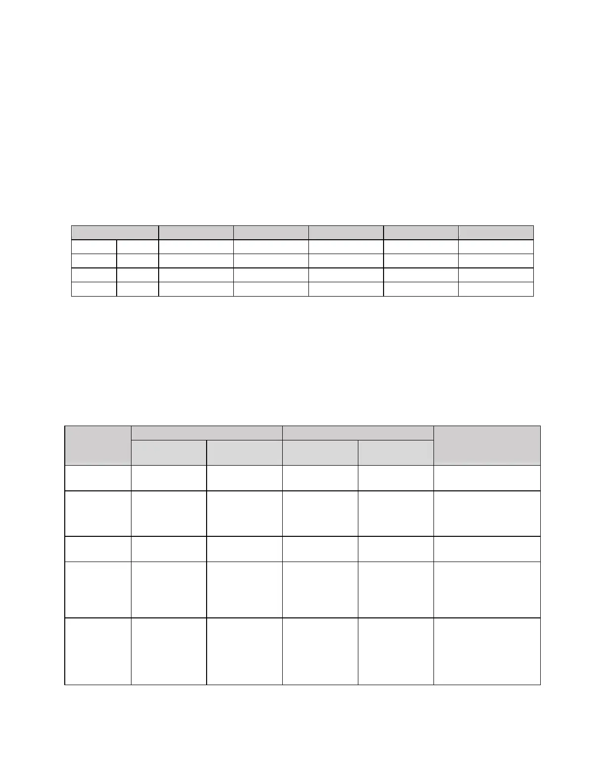
mounting location. Refer to Table 7 below for unit dimensions and weights by model number.
Table 7: Dimensions and Weight by Model Number
Model
11V1T3
11V1B3
15V1T4
15V1B4
28V1B5/28V2B5
Width
in (mm)
44-15/16 (1141)
45-5/8 (1159)
53-3/8 (1355)
53-1/2 (1359)
57-1/2 (1461)
Depth
in (mm)
27-13/16 (706)
27-5/16 (694)
35-7/8 (911)
31-1/4 (794)
42-5/16 (1075)
Height
in (mm)
92-15/16 (2361)
84-9/16 (2148)
92-15/16 (2361)
83-1/16 (2110)
96-3/8 (2448)
Weight
lbs (kg)
645 (293)
645 (293)
858 (390)
840 (380)
1370 (621)
Clearances
The recommended clearances shown below should be adhered to when possible. Units will not be able to
operate correctly if minimum clearances are not met.
Note: The 28V1B5 unit requires a larger side clearance than other bottom supply units.
Table 8: Installation Clearances
Clearance
Top Supply Units
Bottom Supply Units
Comments
Recommended
Minimum
Recommended
Minimum
Front
80 in
(2000 mm)
80 in
(2000 mm)
48 in
(1200 mm)
48 in
(1200 mm)
Clearance between unit
and solid obstructions.
Side
28 in
(700 mm)
16 in
(400 mm)
16 in (400 mm)
28V1 Requires
24 in (600 mm)
8 in (200 mm)
28V1 Requires
16 in (400 mm)
Also minimum spacing
between units
Above
20 in
(500 mm)
12 in
(300 mm)
40 in
(1000 mm)
40 in
(1000 mm)
Supply Air
36 in
(920 mm)
24 in
(600 mm)
36 in
(920 mm)
24 in
(600 mm)
Recommended clearance
applies to complete
blockages in front of the
supply grille, minimum for
partial blockages
Bottom
NA
NA
12 in
(300 mm)
6 in
(150 mm)
Enough space to allow
access to evaporator drain
tube.
NOT needed for 28V1 due
to support stand
mounting.

Table of Contents

Related product manuals