Contact: AIRSYS North America Phone: (855) 874-5380 Page 33 of 112
Email: ASNSupport@air-sys.com Web: http://airsysnorthamerica.com Rev 1.15
Electrical Connection to Controller Box
Important. The ethernet cable used must be wired according to ANSI/TIA-568-B.2 standard.
Communication errors may occur if the cable is not wired correctly.
Follow these steps to complete the connections:
1. Open the controller box.
2. Connect the power cable to the controller breaker (QF1).
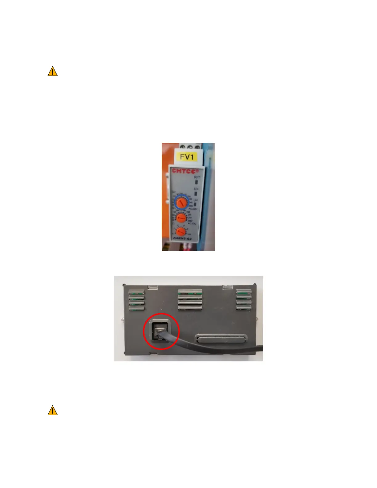
3. (Optional, ASMUC.6.AC Only) If using 240VAC to power the controller, adjust the U> setting on the
voltage monitor to 260V.
4. Ensure the PGD cable is FIRMLY plugged into the user interface terminal located on the inside of the
controller box cover.
5. Ensure that terminal J3 (behind J10) is securely plugged in to the control module.
6. Connect one ethernet cable per unit from a port on the network switch to the control module inside
the unit (Behind J12).
Important. Do not run the Ethernet cables in the same conduit as prime power or other high
voltage AC as this can result in communication errors.