Contact: AIRSYS North America Phone: (855) 874-5380 Page 44 of 112
Email: ASNSupport@air-sys.com Web: http://airsysnorthamerica.com Rev 1.15
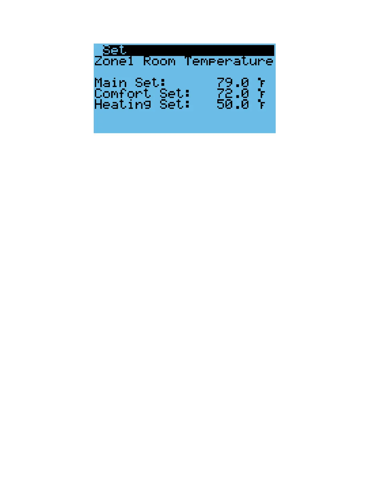
Figure 20: Verify the Main Setpoint
Verify Input and Output Alarms
1. Verify Generator Signal
Note: If the alarm input logic is set incorrectly (NC/NO), no more than one unit will be permitted to
run at any time.
a. Place a jumper between wires 5 and 42 on the controller box terminal block.
b. Press the Alarm button. The generator run alarm should be displayed in the alarm screen.
c. Remove the jumper.
2. Verify Smoke/Fire Alarm Signal
a. Press the test button on the smoke/fire detector. The system should completely shut
down (Fans and compressors off, damper closed, the Smoke/fire alarm will be displayed
on the alarm screen).
b. The Smoke/Fire Alarm is connected to 41 and 5 on the controller terminal block. If the
smoke/fire detector does not have a test button, remove one of the wires from terminals
41 and 5; the system should shut down. It may take the compressor 30 seconds to stop.
3. Verify HVAC Alarms
a. Verify that the negative leads are landed on the alarm common (terminal 47).
b. HVAC1: Turn off the HVAC 1 prime power breaker at panel or unit. Verify alarm signal
between terminals 46 and 47.
a. HVAC2: Turn off the HVAC 2 prime power breaker at panel or unit. Verify alarm signal
between terminals 47 and 48.
b. HVAC3: Turn off the HVAC 3 prime power breaker at panel or unit. Verify alarm signal
between terminals 47 and 49.