Publication 1394-5.0 — May 2000
2-14 Installing Your 1394 (applies to all systems)
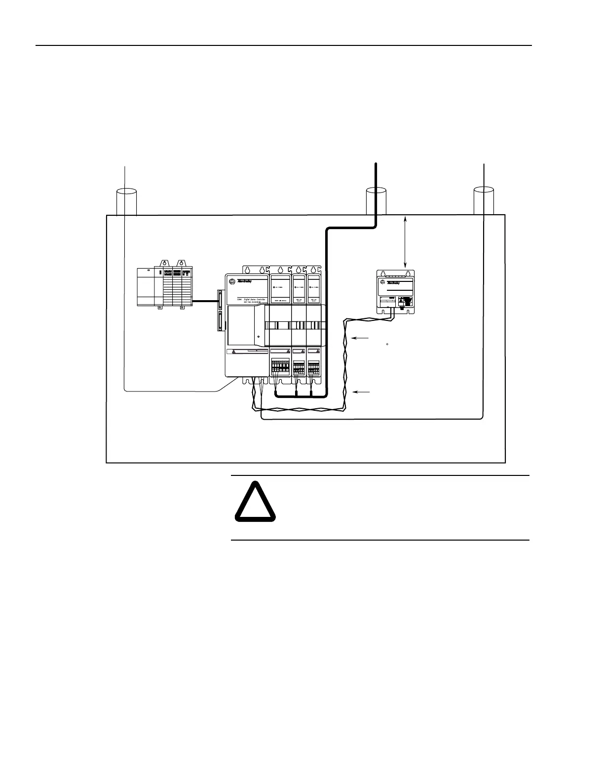
Shunt Module Mounted Inside the Cabinet
The illustration below details the proper position and cable routes for
mounting the shunt module inside the cabinet.
Figure 2.14
Shunt Module Mounted Inside of the Cabinet
!
ATTENTION: If you choose to mount the shunt
module inside your cabinet, you must make sure that
the ambient temperature inside the cabinet does not
exceed 50° C (122° F).
Status
Low voltage
Communications
Control I/O wiring
Motor feedback cables
360/480V
AC power
Always separate all low voltage signal
wiring from high voltage power wiring to
reduce affects of EMI and RFI.
Motor power
cables
155 mm (6.1 in.) of
clearance on all sides
of the shunt module
minimum
Use twisted conductors
(2 twists per foot) min. or
a shielded twisted pair.
8 AWG (8.4 mm
2
),
105 C, 600V wire
Max. Length 3.05 m
(10 ft) for each wire
1394 Digital Servo Controller
300W Shunt Module
BULLETIN 1394 300W SHUNT MODULE
ALLEN-BRADLEY
FOR USE WITH 1394-SJT22-X SYSTEM MODULE
CAT. PART SER.
INPUT DC INPUT AC
FOR FUSE REPLACEMENT USE:
BUSSMAN CAT. NO.
R
Shielding is recommended
for reducing the effects
of EMI and RFI.
DANGER
RISK OF ELECTRICAL SHOCK. HIGH VOLTAGE MAY
EXIST UP TO FIVE MINUTES AFTER REMOVING POWER.

 Loading...