Publication 1394-5.0 — May 2000
Interconnect and CE Diagrams B-3
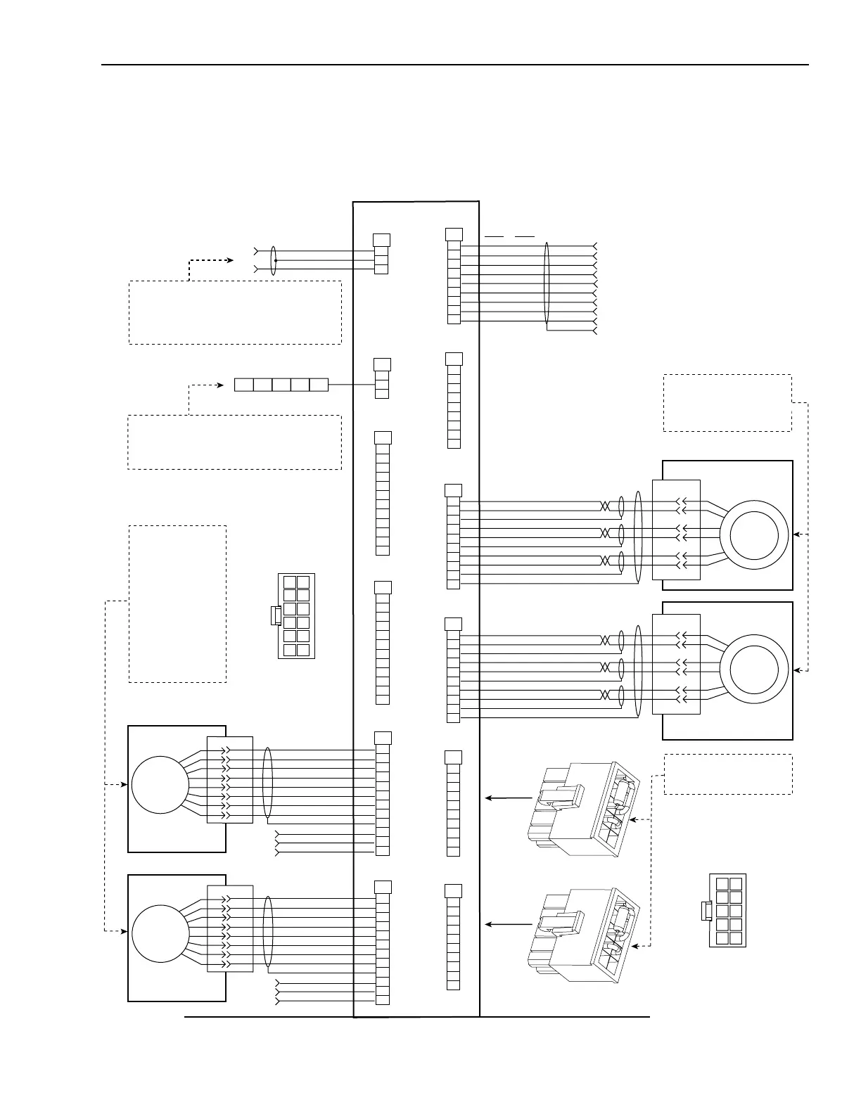
1394 GMC Interconnections
Figure B.1
Bottom Front of the GMC (1394
x
-SJT
xx
-C) and
GMC Turbo (1394
x
-SJT
xx
-T) System Modules
FLEX I/O MODULES
NC
TXD
RXD
DTR
COM
DSR
RTS
CTS
NC
RS-232
TXD+
TXD–
RXD–
TXD+
COM
TXD+
RXD+
RXD+
NC
RS-422
NOTE 10, 18
WIRE #1 - BLACK - AXIS X R1
WIRE #1 - WHITE - AXIS X R2
WIRE #1 - SHIELD
WIRE #2 - BLACK - AXIS X S1
WIRE #2 - RED - AXIS X S3
WIRE #2 - SHIELD
WIRE #3 - BLACK - AXIS X S4
WIRE #3 - GREEN - AXIS X S2
WIRE #3 - SHIELD
CABLE SHIELD
CHANNEL A HIGH
CHANNEL A LOW
CHANNEL B HIGH
CHANNEL B LOW
CHANNEL Z HIGH
CHANNEL Z LOW
+5V OUT
COMMON OUT
SHIELD
STROBE X
+5V INPUT
COMMON INPUT
C LEAR
SHIELD
BLUE
J10
1
6
2
3
8
7
9
4
5
10
Resolver
Feedback Input
Resolver
Feedback Input
J7
1
6
2
3
8
7
9
4
5
10
J6
1
6
2
3
8
7
9
4
5
10
J5
1
6
2
3
8
7
9
4
5
10
J3
1
2
3
4
5
6
7
8
9
RS-232/RS-422
J4
1
2
3
4
5
6
7
8
9
RS-232/RS-422
DH-485
J10
1
2
3
4
5
6
8
9
12
7
10
11
Aux. Encoder
Feedback Input
Aux. Encoder
Feedback Input
Resolver
Feedback Input
Resolver
Feedback Input
Aux. Encoder
Feedback Input
Aux. Encoder
Feedback Input
J5
1
2
3
4
5
6
8
9
12
7
10
11
J4
1
2
3
4
5
6
8
9
12
7
10
11
J3
1
2
3
4
5
6
8
9
12
7
10
11
J2
Flex I/O
J1
1
2
AxisLink
A
B
D
E
H
G
MOTOR
RESOLVER
Encoder (Optional)
Auxiliary
Encoder
A
H
B
I
C
J
D
F
J5 wiring is typical for J6, J7,
and J10 Resolver inputs. Use
either Allen-Bradley Resolver
cable (1326-CCU-
xxx
) or
1394-DIM plug.
1
6
7
12
ENCODER CONNECTOR
(DRIVE END)
BOTTOM VIEW
Left Side
Right Side
AXIS 0
AXIS 1
AXIS 2
AXIS 3
AXIS 0
AXIS 1
AXIS 2
AXIS 3
CHANNEL A HIGH
CHANNEL A LOW
CHANNEL B HIGH
CHANNEL B LOW
CHANNEL Z HIGH
CHANNEL Z LOW
+5V OUT
COMMON OUT
SHIELD
STROBE X
+5V INPUT
COMMON INPUT
Encoder (Optional)
Auxiliary
Encoder
A
H
B
I
C
J
D
F
WIRE #1 - BLACK - AXIS X R1
WIRE #1 - WHITE - AXIS X R2
WIRE #1 - SHIELD
WIRE #2 - BLACK - AXIS X S1
WIRE #2 - RED - AXIS X S3
WIRE #2 - SHIELD
WIRE #3 - BLACK - AXIS X S4
WIRE #3 - GREEN - AXIS X S2
WIRE #3 - SHIELD
CABLE SHIELD
1326A
x
AC SERVO MOTOR
A
B
D
E
H
G
MOTOR
RESOLVER
Plug into
connector
Plug into
connector
The RIO/AxisLink option (-RL) must be ordered with
System module. It is installed at the factory. You cannot
order these individually.
AxisLink and RIO board connections use Allen-Bradley
1770-CD (Belden 9463 or equivalent).
Use 4100-CCF1 or -CCF3 Flex I/O cables. Cable length
must not exceed 0.91 mm (36 inches).
You must supply source power for Flex I/O (for example,
1794-IB16 24V DC and 1794-IA8 115V AC).
1394-GE15 Cable
Optional Encoder
or 1394-GR04 Cable
(for Resolver with
4100-REC or 4100-AEC
modules)
J5 wiring is typical for J3,
J4, and J10 Auxiliary
Encoder Inputs.
User-supplied 5V DC
power source is required
for encoder board
regardless if encoder
supply voltage is 5V or
not.
One 1394-DIM plug is required
for each DIM axis. Four plugs
are supplied with the DIM.
16
RESOLVER CONNECTOR
(DRIVE END)
BOTTOM VIEW
510
1326A
x
AC SERVO MOTOR

 Loading...