Publication 1394-5.0 — May 2000
4-14 Wiring 1394 GMC and GMC Turbo Systems
AxisLink
AxisLink provides a network to transfer data between multiple nodes
(up to eight standard) that allows you to synchronize complex motion
applications. For example, these nodes can be eight GMC system
modules, one ALEC and 7 GMC system modules, or some other
combination. AxisLink allows one 1394 to be used as a master axis
for electronic gearing, camming, etc. on other systems. Using the
Extended Node option in GML version 3.9.1 (or higher) with
firmware version 3.5 (or higher) you can link up to 16 nodes. Connect
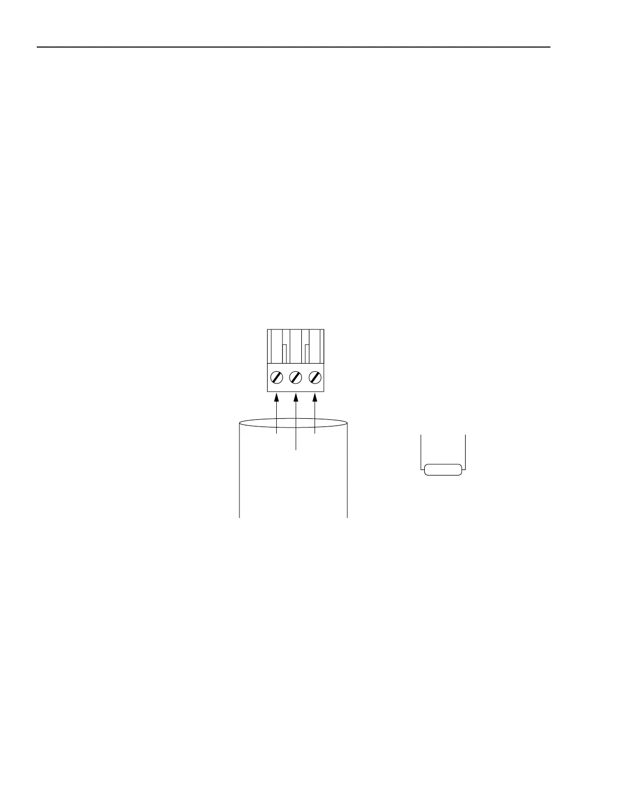
the AxisLink cable to J1 with a three pin connector as shown in
Figure 4.12. The maximum end-to-end length for Daisy-Chain
cabling configurations is 25 m (82 ft). The minimum distance
between AxisLink nodes is 0.9 m (3 ft). Refer to Figures 4.7 and 4.8
for the AxisLink connector’s location.
Figure 4.12
AxisLink Connections for a GMC System
Important: All nodes on the same AxisLink network should be
operated at the same servo update rate.
Important: Select your AxisLink node address (0-7) using the front
panel switch (see Figure 4.6 for the switch’s location)
(standard mode only). Do not use positions 8 or 9.
2
1
Clear
Shield
Blue
Required cable
AB 1770-CD
(Belden 9463 or equivalent)
150 ohm
Install a 150 ohm termination resistor
across 1 and 2 if this is the first or last
module on the line.
AxisLink Connector
Connects to J1

 Loading...