Publication 1394-5.0 — May 2000
A-18 Specifications
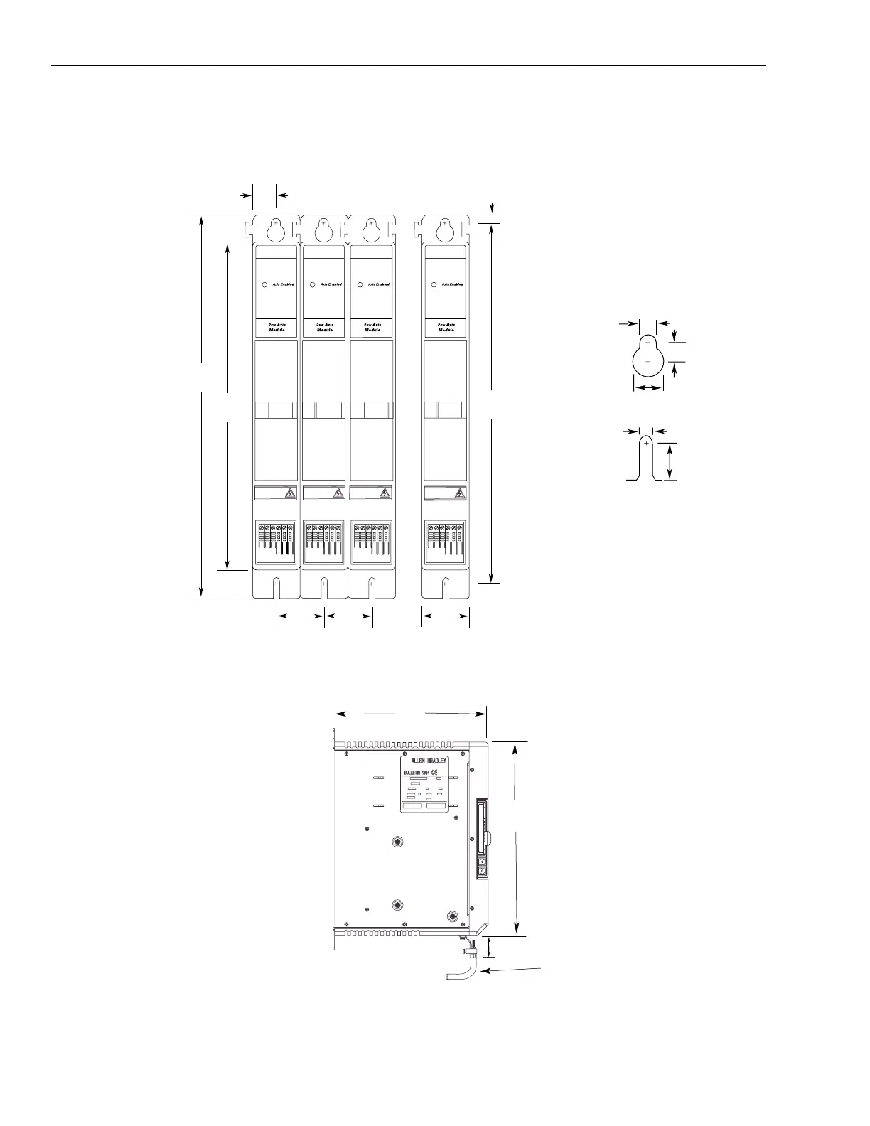
Axis Module Dimensions
Figure A.4
1394
x
-AM03, -AM04, -AM07, -DIM, and -DCLM Front View
Figure A.5
1394
x
-AM03, -AM04, -AM07, -DIM, and -DCLM Side View
350.0
(13.78)
400.0
(15.75)
50.0
(1.97)
25.0
(0.98)
50.0
(1.97)
50.0
(1.97)
Dimensions are in millimeters and (inches)
All slots accept M6 or 1/4-20 mtg. screws
Mounting Hole Detail
12.0 (0.47)
385.0
(15.16)
8.0 (0.31)
8.0 (0.31)
10.1 (0.40)
15.9 (0.63)
8.0 (0.32)
Fastener
location
1
1
Dimension shown is for mounting hardware
location and does not reflect the location of
the lower slot radius.
350
(13.78)
280
(11.02)
Dimensions are in millimeters and (inches)
40.13
(1.58)
Important: Additional clearance below the axis
is necessary to provide the recommended cable
bend radius. Refer to
1326 Cables for 460V AC
Servo Motors
(publication 1326A-2.11) for more
information.

 Loading...