Publication 1394-5.0 — May 2000
Interconnect and CE Diagrams B-19
1394 GMC Systems (1394C-SJT
xx
-L)
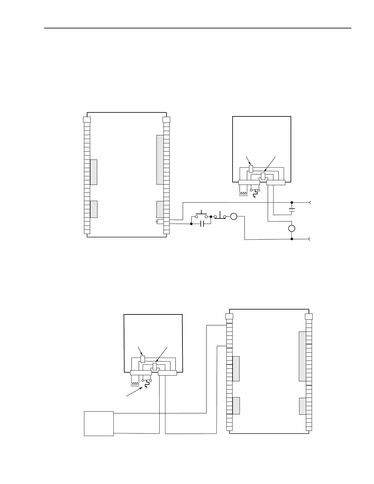
The example below shows a 1394 (Series C) axis module with
internal brake and thermal switch filtering. Separate isolation power
supply and relay are not required.
Figure B.12
Non-Isolated Series E-Stop
The example below shows a 1394 (Series C) axis module wired for
thermal fault monitoring. The fault can be used to monitor or disable
the axis.
Figure B.13
Non-Isolated Series E-Stop with Thermal Fault Monitoring
Axis 0
24V AC/DC
or
120V AC,
50/60 HZ
STOP
START
CR1
CR1
CR1
M1
Drive OK
Relay
1394 GMC Input Wiring Board
1394C-SJT
xx
-L
1394C-SJT
xx
-L-RL
TB2
1
2
3
4
5
6
7
8
9
10
11
12
13
14
15
16
17
18
19
20
TB1
1
2
3
4
5
6
7
8
9
10
11
12
13
14
15
16
17
18
19
20
21
22
23
24
25
26
27
21
22
23
24
25
26
27
Shaded areas on TB1 and TB2
designate signals not used on the
1394C-SJT
xx
-L and
1394C-SJT
xx
-L-RL
system modules.
TB1
Motor brake
filter (Series C)
Motor thermal
switch filter
(Series C)
TB2
1394C-AM
xx
4 3 2 1
4 3
4 3 2 1
24V DC
I/O
Power Supply
+24V DC
24V DC com
THERM FLT 0
Axis 0
Motor
Thermal
Switch
Note: 120V AC (50 or 60 Hz) power may be used in place of a 24V DC power supply for the motor thermal switch circuit.
1394 GMC Input Wiring Board
1394C-SJT
xx
-L
1394C-SJT
xx
-L-RL
TB2
1
2
3
4
5
6
7
8
9
10
11
12
13
14
15
16
17
18
19
20
TB1
1
2
3
4
5
6
7
8
9
10
11
12
13
14
15
16
17
18
19
20
21
22
23
24
25
26
27
21
22
23
24
25
26
27
Shaded areas on TB1 and TB2
designate signals not used on the
1394C-SJT
xx
-L and
1394C-SJT
xx
-L-RL
system modules.
TB1
Motor brake
filter (Series C)
Motor thermal
switch filter
(Series C)
TB2
1394C-AM
xx
4 3 2 1
4 3
4 3 2 1

 Loading...