Publication 1394-5.0 — May 2000
B-20 Interconnect and CE Diagrams
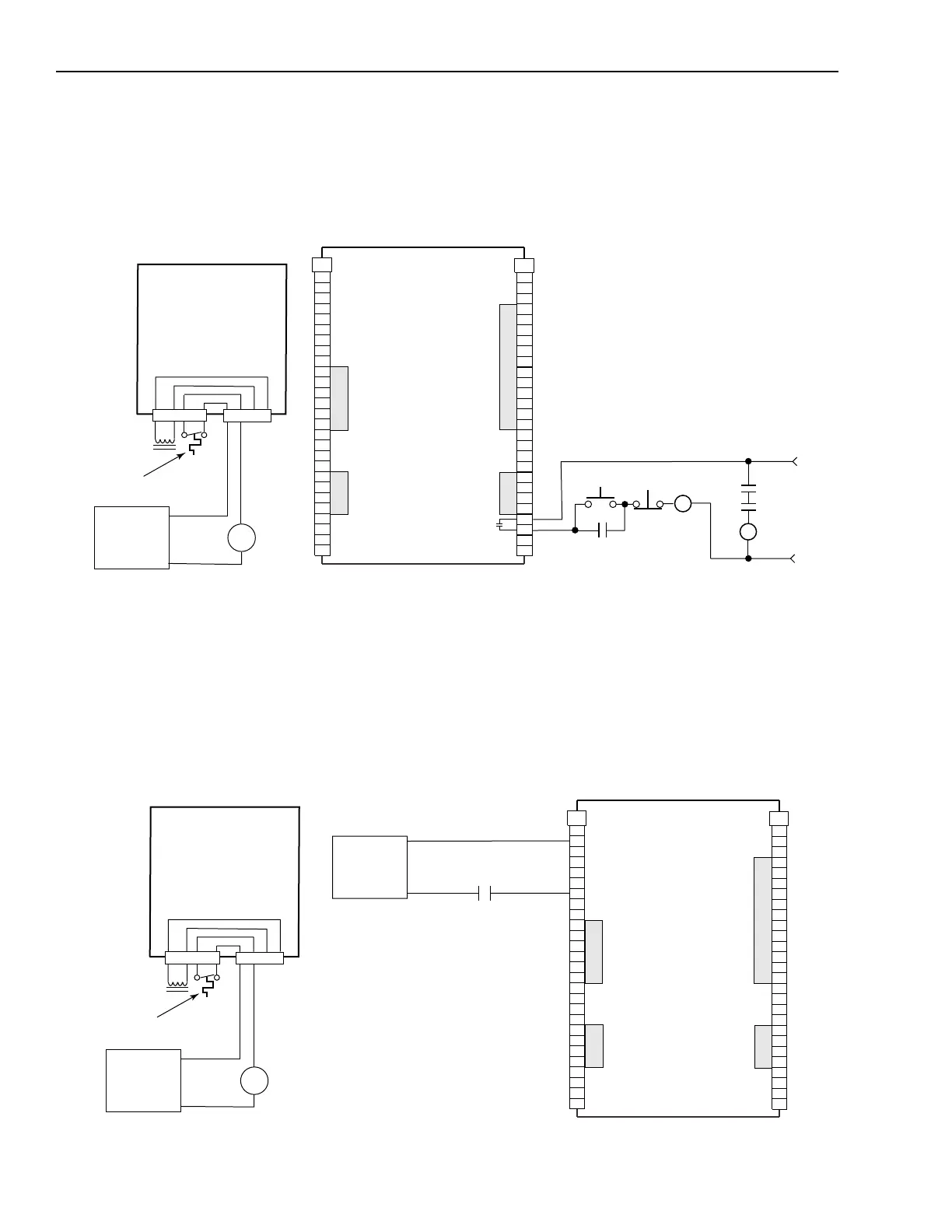
The example below shows a 1394 (Series A and B) axis module (no
internal brake and thermal switch filter). Separate 24V DC isolation
power supply and relay (CR2) are recommended.
Figure B.14
Isolated Series E-Stop
The example below shows a1394 (Series A and B) axis module wired
for thermal fault monitoring. The fault can be used to monitor or
disable the axis. Separate 24V DC power supply and isolation relay
(CR2) are included to filter conducted noise.
Figure B.15
Isolated Series E-Stop with Thermal Fault Monitoring
Axis 0
1394 GMC Input Wiring Board
1394C-SJT
xx
-L
1394C-SJT
xx
-L-RL
TB2
1
2
3
4
5
6
7
8
9
10
11
12
13
14
15
16
17
18
19
20
TB1
1
2
3
4
5
6
7
8
9
10
11
12
13
14
15
16
17
18
19
20
21
22
23
24
25
26
27
21
22
23
24
25
26
27
24V DC
Power Supply
+24V DC
24V DC com
CR2
Note: 120V AC (50 or 60 Hz) power may be used in place of a 24V DC power supply for the motor thermal switch circuit.
Drive OK
Relay
24V AC/DC
or
120V AC,
50/60 HZ
STOP
START
CR1
CR1
CR1
M1
CR2
Shaded areas on TB1 and TB2
designate signals not used on the
1394C-SJT
xx
-L and
1394C-SJT
xx
-L-RL
system modules.
Motor
Thermal
Switch
TB1
TB2
1394-AM
xx
4 3 2 1
4 3
4 3 2 1
Axis 0
24V DC
Power Supply
+24V DC
24V DC com
CR2
Note: 120V AC (50 or 60 Hz) power may be used in place of a 24V DC power supply for the motor thermal switch circuit.
24V DC
I/O
Power Supply
+24V DC
24V DC com
THERM FLT 0
1394 GMC Input Wiring Board
1394C-SJT
xx
-L
1394C-SJT
xx
-L-RL
TB2
1
2
3
4
5
6
7
8
9
10
11
12
13
14
15
16
17
18
19
20
TB1
1
2
3
4
5
6
7
8
9
10
11
12
13
14
15
16
17
18
19
20
21
22
23
24
25
26
27
21
22
23
24
25
26
27
Shaded areas on TB1 and TB2
designate signals not used on the
1394C-SJT
xx
-L and
1394C-SJT
xx
-L-RL
system modules.
Motor
Thermal
Switch
TB1
TB2
1394-AM
xx
4 3 2 1
4 3
4 3 2 1

 Loading...