Publication 1394-5.0 — May 2000
Specifications A-11
DC Link Module
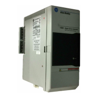
The power dissipation for the 1394-DCLM is shown below.
Drive Interface Module
The power dissipation for the 1394-DIM is shown below.
Internal Shunt Resistor for the 5 and 10 kW System (standard)
When the shunt resistor inside 1394x-SJT05 and 1394x-SJT10 system
module is active, some additional power will be dissipated at the
system module. Its maximum dissipation is 200W. Most applications
will use less than 10% of this capacity.
Communication Specifications
The communication specifications are listed in the tables starting
below.
Encoder Input Specifications
The table below lists the encoder input specifications for the system
module (1394x-SJTxx-C-xx, -L-xx, and -T-xx systems).
The: For the 1394-DCLM is:
Power dissipation 4.225 W maximum
The: For the 1394-DIM is:
Power dissipation 30 W maximum
The: Is:
Rating of the internal shunt resistor 200W continuous, 40,000W peak (two second
maximum on time)
Resistance of the internal shunt resistor 16 ohms
The: Is:
Number of encoder inputs 4 (axis 0, 1, 2, and 3) for 1394
x
-SJT
xx
-C-
xx
and -T-
xx
systems
2 (axis 0 and 1) for 1394C-SJT
xx
-L-
xx
systems
Type of encoder input Incremental AB quadrature; optically isolated, differential
with marker channel
Encoder interface IC AM26LS32 or equivalent
Compatible encoder types Differential, TTl-level (5V DC) line driver outputs, with or
without marker
Decode modes 4 times quadrature, step/direction, count up/count down
Maximum encoder frequency 4,000,000 counts per second (4 MHz). This is equivalent to
a channel frequency of 1 MHz in 4x quadrature decode mode.
Input impedance 7 kohms minimum (each input)
Encoder power 5V DC @ 1A, user supplied

 Loading...