Publication 1394-5.0 — May 2000
Chapter
5
Wiring Your 1394 Analog Servo
System
Chapter Objectives
This chapter covers the following topics:
• Understanding Analog Servo wiring and connections
• Understanding input wiring board layout
• Connecting AQB and SCANport cables
Finding Additional Wiring
Information for 1394 Systems
This chapter provides signal wiring and connection information required
for the 1394 Analog Servo system module only.
Understanding Analog Servo
Wiring and Connections
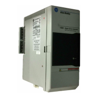
The Analog Servo system module contains all of the components needed
for an analog servo control system. The module provides connectors for
the following:
• Motor feedback (resolver)
• AQB output and torque/velocity reference input to and from a motion
controller
• Serial communications for the HIM module
For additional wiring
information on:
Refer to the following:
GMC or GMC Turbo
system modules
Chapter 4 (Wiring 1394 GMC and GMC Turbo Systems)
in this
manual.
CNC Interface or
9/440 system modules
9/Series CNC Hardware Integration and Maintenance Manual
(publication 8520-6.2).
1394 SERCOS system
modules
1394 SERCOS Multi-Axis Motion Control System User Manual
(publication 1394-5.20)

 Loading...