Publication 1394-5.0 — May 2000
Wiring 1394 GMC and GMC Turbo Systems 4-21
Figure 4.20
1394-DIM to J1 Breakout Board Pinouts
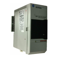
1394-DIM Configurations
The identity and number of the axes you can connect to a 1394-DIM
depends upon the number of 1394 axis modules connected to your
1394 system in addition to the 1394-DIM.
The figure below shows the input connections located on the bottom
of a typical 1394 system and a 1394-DIM.
Figure 4.21
A 1394-DIM Connected to a GMC or GMC Turbo
A 1394x-SJTxx-C, -C-RL, -T, and -T-RL system module can control
a maximum of four physical axes. The 1394C-SJTxx-L and -L-RL
can control only one axis. Each 1394 axis module added to the 1394
system reduces the number of external drives and axes the 1394-DIM
can control by one.
24V I/O
Power Supply
1
1394-DIM Cable Connector
Belden 8163
cable or equivalent
J1 Breakout Board
1
Required on ULTRA 100 only
2
x
= axis controlled by DIM
2
+ Analog Out P
x
-1
– Analog Out P
x
-2
– Drive Enable P
x
-3
+ Drive Enable P
x-
4
+ DROK P
x
-5
– DROK P
x
-6
Shield P
x
-7
J1-22 CMND +
J1-23 CMND -
J1-20 Enable
J1-26 I/O PWR
J1-25 Ready -
J1-24 Ready +
J1-5
J1-6
Rear of the units
Front of the units
Bottom of the
1394-DIM
Bottom of the
1394 GMC or 1394
GMC Turbo System
1394-DIM ground connector

 Loading...