Publication 1394-5.0 — May 2000
Wiring System, Axis, and Shunt Modules, and Motors (for all systems) 3-27
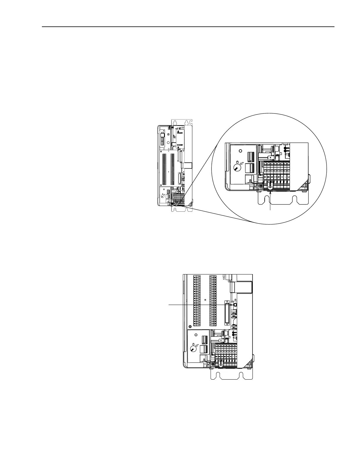
Connecting Your External Shunt Resistor (Series A and B)
1. Open the front door of the 1394 system module.
2. Remove and discard the COL/INT jumper wire from the power
terminal block in the lower right corner, as shown in the figure
below.
Figure 3.15
1394 System Module Jumper Removal (Series A and B)
3. Install the jumper block in the P1 position, which is located
directly behind the Status LED, as shown in the figure below.
Figure 3.16
1394 System Module Jumper Installation (Series A and B)
4. Install and tighten the resistor wire with the fuse in the DC+
terminal on the power terminal block in the lower right corner.
5. Install and tighten the other resistor wire in the COL terminal on
the power terminal block in the lower right corner.
Jumper
Jumper
block to P1

 Loading...