Publication 1394-5.0 — May 2000
Wiring System, Axis, and Shunt Modules, and Motors (for all systems) 3-15
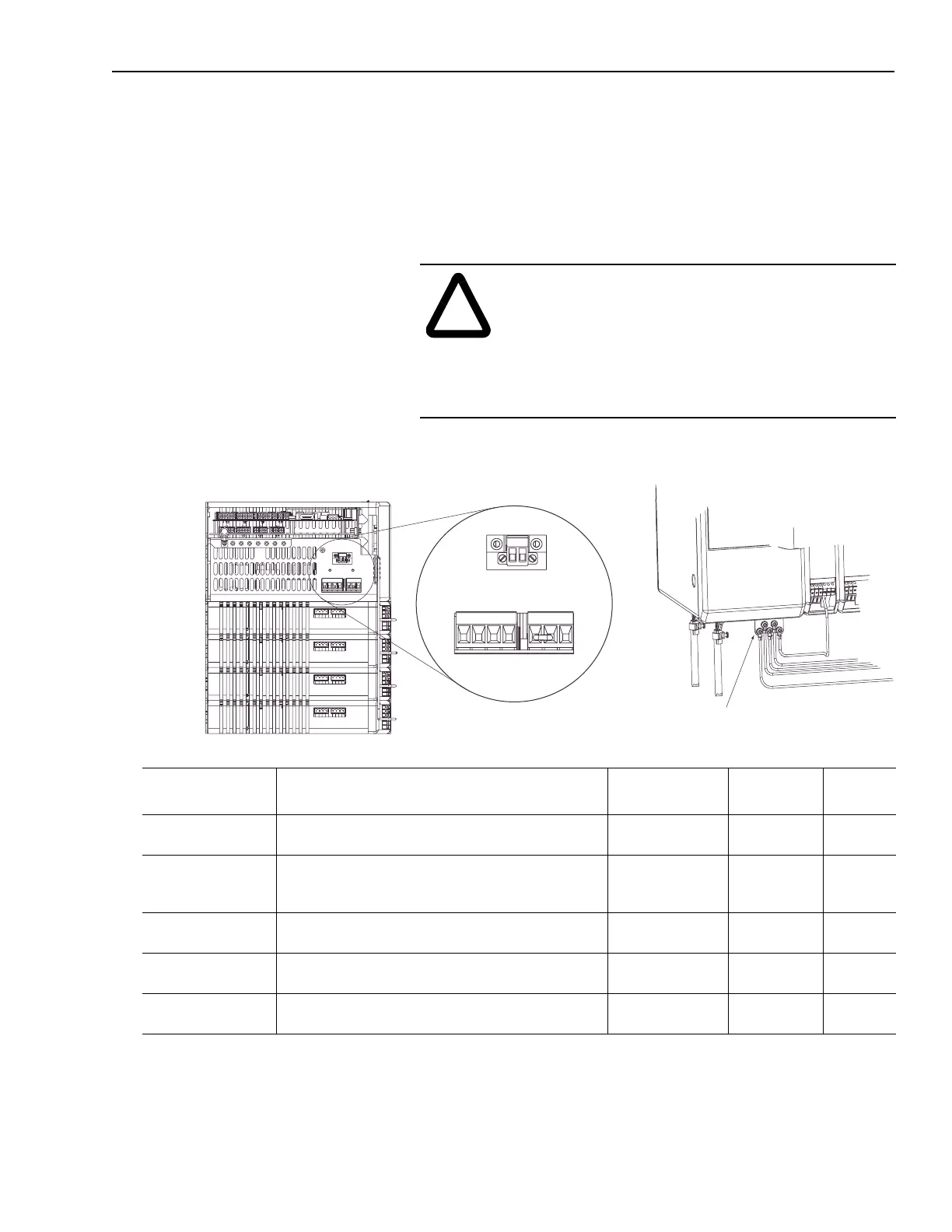
Connector Locations for 5 and 10 kW System Module (Series C)
The 5 and 10 kW system module (Series C) uses connectors instead
of IEC terminals for connecting power. You will wire the system
using power connectors (J1, J10, and J11) that mate with plugs (P1,
P10, and P11) conveniently located on the bottom of the system
module. Figure 3.11 details the location of the connectors.
Figure 3.11
Connectors for 5 and 10 kW System Module (Series C)
Note: Refer to Appendices A and B for information about three-phase
input fusing and circuit breaker information as related to the
power input. Refer to the section Connecting Your External
Shunt Resistor for information about wiring the optional shunt
resistor to the 5 and 10 kW system modules.
!
ATTENTION: To avoid personal injury and/or
equipment damage ensure installation complies with
specifications regarding wire types, conductor sizes,
branch circuit protection, and disconnect devices. The
National Electrical Code (NEC) and local codes
outline provisions for safely installing electrical
equipment.
Wire: Description: Maximum wire size:
Connects to
terminal(s):
Required
(Y/N):
24V Logic A user-supplied 24V AC rms or 24V DC power source. Refer to
Appendix A
for 24V input power specifications.
3.3 mm
2
(12 AWG)
J1-1 and
J1-2
Y
360/480V AC Input
Power
360/480V AC, three-phase power input Refer to
Appendix A
for
system specifications for rated AC input voltage, tolerance, and
source impedance.
5.3 mm
2
(10 AWG)
J10-1 (U)
J10-2 (V) and
J10-3 (W)
Y
Input Power Neutral Three-phase input neutral (present only on grounded power
configurations).
5.3 mm
2
(10 AWG)
J10-4 N
PE Ground The1394’s ground connection to the bonded system ground bar
on the subpanel.
8.4 mm
2
(8 AWG)
System module
ground bar
Y
External Shunt Resistor Optional 1400W external shunt resistor used to dissipate
excess regenerative energy from the system module.
5.3 mm
2
(10 AWG)
J11-3 and
J11-1
N
1394 front view
System module
ground bar
1 2 3 4
1 2 3
J10
J11
1 2
J1
1394 bottom view

 Loading...