Publication 1394-5.0 — May 2000
4-20 Wiring 1394 GMC and GMC Turbo Systems
1394-DIM with 1398-DDM-
xxx
System Example
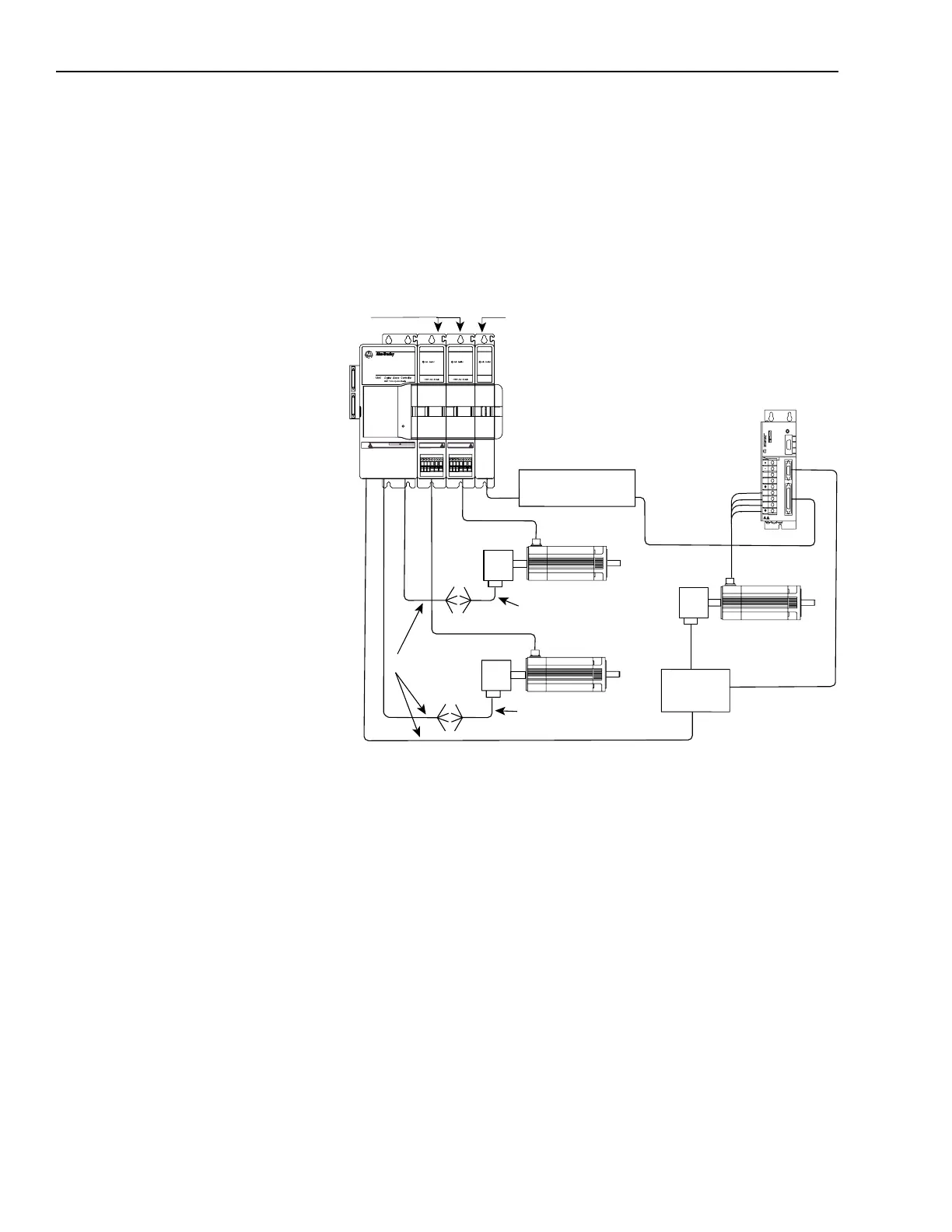
Figure 4.19 shows the 1394-DIM connected to a 1394 GMC Turbo
with two 1394 axis modules and a 1398-DDM-xxx servo controller. A
1326AB-Bxxxx motor is directly connected to each of the 1394 axis
modules. One servo amplifier with motor is connected to the
1394-DIM.
Figure 4.19
1394-DIM with 1398-DDM-
xxx
System Example
Figure 4.20 shows the J1 breakout board interconnect details between
the 1394-DIM and the 1398-DDM-xxx. Refer to ULTRA 200 User
Manual (publication 1398-5.0) and ULTRA 100 User Manual
(publication 1398-5.2) for more information.
!
?
J5
J2
J1
TB1
1394 GMC or GMC
Turbo System Module
Status
Encoder
1326AB
1394 Axis Modules
1394-DIM
Encoder
H, F, Y, or N
Series Motor
1394-GE15
9101-1392
Axis 1
Axis 0
1398-DDM-
xxx
J1
J2
Motor
Power
J2 Breakout
Board
1326AB
Encoder
J1 Breakout Board
(Refer to Figure 4.20)
9101-1391
Axis 2
1326-CEU-
xxx
(If A-B 845H)
1326-CEU-
xxx
(If A-B 845H)
DANGER
RISK OF ELECTRICAL SHOCK. HIGH VOLTAGE MAY
EXIST UP TO FIVE MINUTES AFTER REMOVING POWER.

 Loading...