Publication 1394-5.0 — May 2000
B-18 Interconnect and CE Diagrams
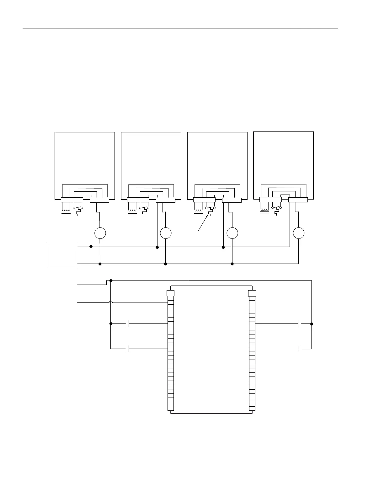
The example below shows 1394 (Series A and B) axis modules wired
for thermal fault monitoring. Depending on how the 1394 GMC
system is configured, the fault can be used to disable one or all of the
four axis modules. Two separate 24V DC power supplies and four
relays (CR2-CR5) are included to isolate the THERM FLT inputs
from conducted noise.
Figure B.11
Isolated Series E-Stop with Thermal Fault Monitoring
CR3
CR2
CR5
TB2
1
2
3
4
5
6
7
8
9
10
11
12
13
14
15
16
17
18
19
20
TB1
1
2
3
4
5
6
7
8
9
10
11
12
13
14
15
16
17
18
19
20
21
22
23
24
25
26
27
21
22
23
24
25
26
27
24V DC
I/O
Power Supply
+24V DC
24V DC com
CR3CR2
CR4
CR5
THERM FLT 1
THERM FLT 3THERM FLT 2
THERM FLT 0
Note: 120V AC (50 or 60 Hz) power may be used in place of a 24V DC power supply for motor thermal switch circuits.
1394 GMC Input Wiring Board
1394
x
-SJT
xx
-C
1394
x
-SJT
xx
-C-RL
AND
1394
x
-SJT
xx
-T
1394
x
-SJT
xx
-T-RL
Axis 0
Axis 1
Axis 2
Axis 3
24V DC
Power Supply
+24V DC
24V DC com
Motor
Thermal
Switch
CR4
TB1
TB2
1394-AM
xx
4 3 2 1
4 3
4 3 2 1
TB1
TB2
1394-AM
xx
4 3 2 1
4 3
4 3 2 1
TB1
TB2
1394-AM
xx
4 3 2 1
4 3
4 3 2 1
TB1
TB2
1394-AM
xx
4 3 2 1
4 3
4 3 2 1

 Loading...