Geometries with orientation support
124 Rockwell Automation Publication MOTION-UM002F-EN-P - February 2018
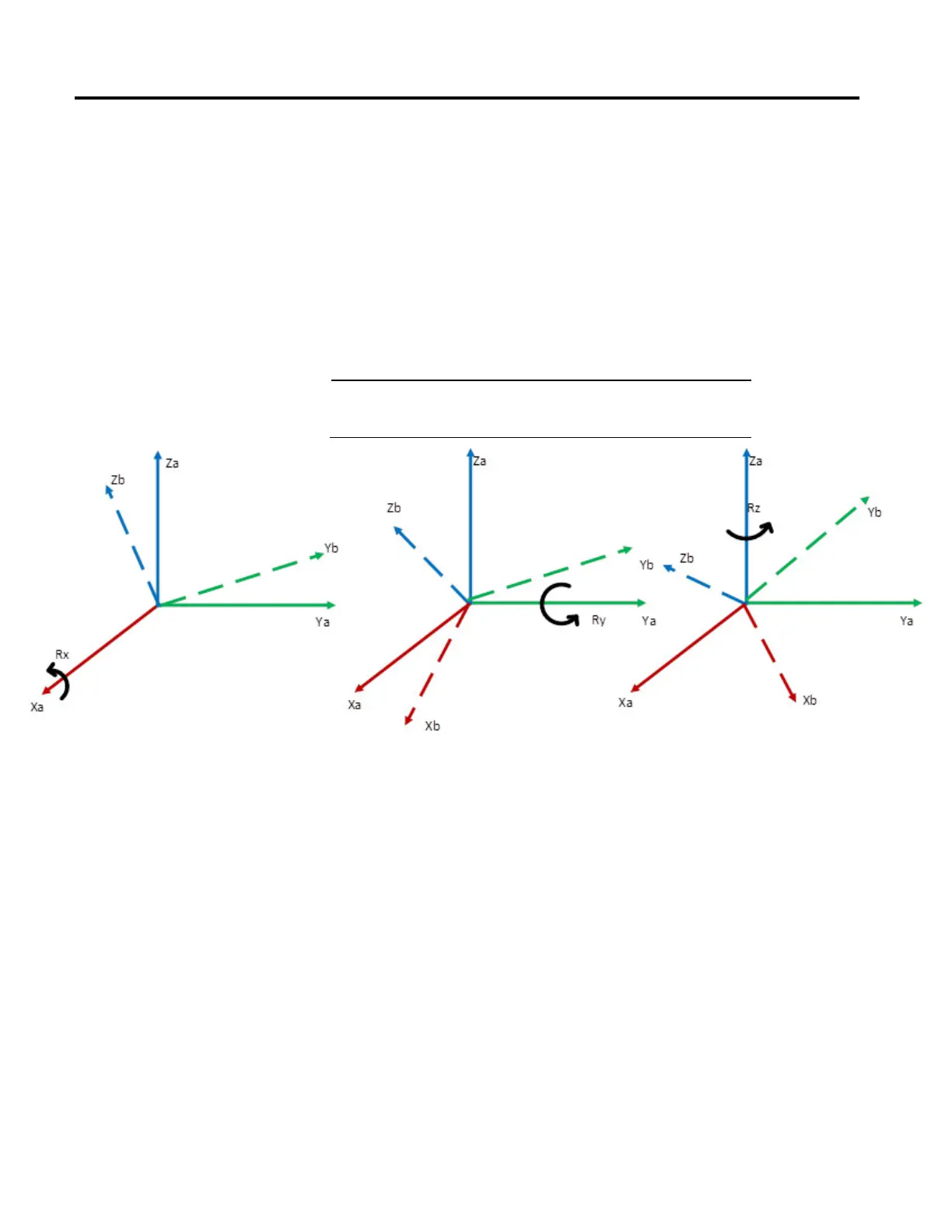
• Start with the frame coincident with a known reference frame {A}.
• Rotate {B} first about X
A
by an angle Rx,
• then about Y
A
by an angle Ry,
• and, finally, about Z
A
by an angle Rz.
Each of the three rotations takes place about an axis in the fixed reference frame
{A}. We call this convention for specifying the orientation X-Y-Z fixed angle. The
word fixed refers to the fact that the rotations are specified about the fixed
reference frame {A} as shown below.
Important:
The Logix firmware uses this convention for specifying the points. Any
point in Cartesian space is specified by 6 numbers XYZRxRyRz where Rx, Ry
and Rz are specified with fixed angle convention.
Start with a frame coincident with reference frame {A}. First rotate {B} about Xa
by an angle γ, then rotate about Ya by an angle β and then rotate about Za by an
angle α. It is also important to note that order of rotation is important which in
this case is X-Y-Z. If this order is changed then orientation will get altered. This
fact is shown in the equation below.
A
B
R(γ ,β,α) = R
Z
(α)R
Y
(β) R
X
(γ)
Euler Angle - Z - Y' - X"
Another possible convention of a frame {B} is as follows
• Start with the frame coincident with a known reference frame {A}.
• Rotate {B} first about Z
B
by an angle Rz,
• then about Y
B
’ by an angle Ry,
 Loading...

