Geometries with orientation support
Rockwell Automation Publication MOTION-UM002F-EN-P - February 2018 139
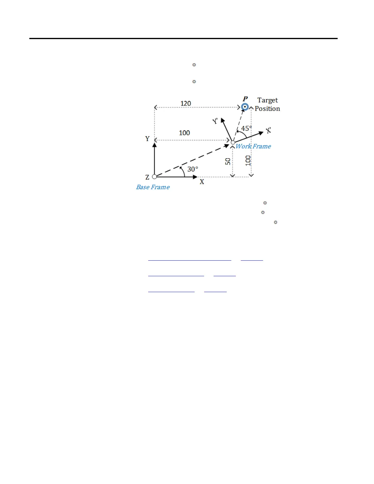
Assume that the target position (P) is measured as P1 (X = 120, Y = 100, Z = 0,
Rx = 0, Ry = 0, Rz = 75
) from the robot’s base frame. Now, with respect to a new
work frame, target position (P) will change as P2 (X = 42.321, Y = 33.301, Z = 0,
Rx = 0, Ry = 0, Rz = 45 ).
Position from the Base Frame (P1):
(X = 120, Y = 100, Z = 0, Rx = 0, Ry = 0, Rz = 75
)
Work Frame Offsets:
(X = 100, Y = 50, Z = 0, Rx = 0, Ry = 0, Rz = 30
)
Position from the Work Frame (P2):
(X = 42.321, Y = 33.301, Z = 0, Rx = 0, Ry = 0, Rz = 45
)
See also
Define coordinate system frames on page 134
Work frame examples on page 139
Tool frame offsets on page 142
These examples illustrate how to use work frames in different scenarios.
Multiple work frames with one robot base frame
Use work frames in scenarios where one robot works with multiple work frames or
multiple robots work with the same work frames. In this example, the target
positions and program remain the same, but the work frame’s offsets change based
on the different work frame positions.
 Loading...

