Geometries with orientation support
178 Rockwell Automation Publication MOTION-UM002F-EN-P - February 2018
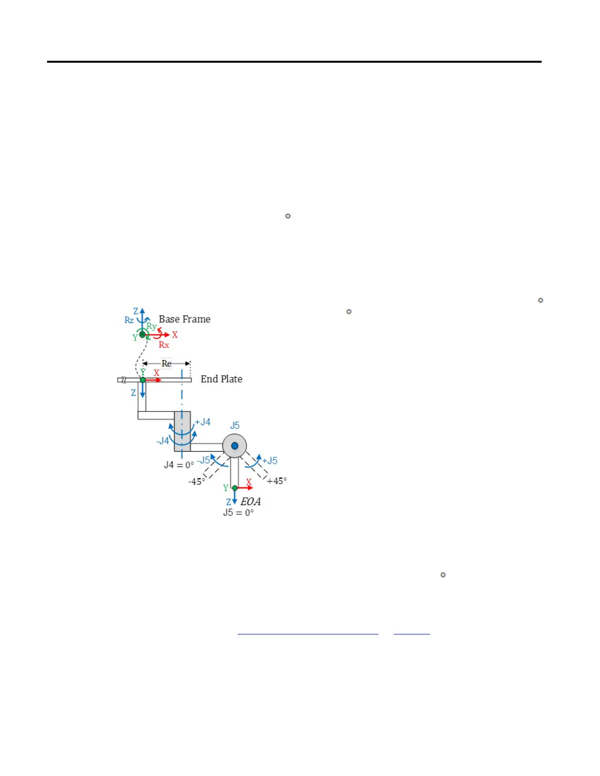
At the EOA, X axis is in the same direction as Base frame X axis and the Z axis
direction is pointing down towards the direction of Tool approach vector.
Joint 4 axis of rotation is aligned with the Z axis of Base frame and Joint 5 axis of
rotation is aligned with Y axis of Base Frame.
• To set the home position for J4 axis, move the J4 and J5 axis such a way that
X axis of EOA is aligned with link L1 of the J1 axis (X axis of Base frame).
• Homing of J5 axis is set with reference to J4 position. When J4 axis is
homed to 0
position, J5 rotation is aligned with the Y axis of Base frame.
At J5 home position, swing arm link (D5) should be vertical aligned with X
axis of Base frame.
The following illustration show axis of rotations and their directions for J4
and J5.
Tip: In case of coupling to prevent tilt motion caused by J4 homing, first home the J4 to 0
then home J5 to 0
with reference to the J4 home position.
• + J4 is measured clock wise around the +Z axis at the Base Frame.
• + J5 is measured counterclockwise around the -Y axis at the Base Frame
(+Y axis is pointing inside) when J4 is homed at 0
position.
See also
Calibrate a Delta J1J2J3J4J5 robot on page 178
Use these steps to calibrate a five-dimensional robot.
Calibrate a Delta J1J2J3J4J5
robot
 Loading...

