Geometries with orientation support
Rockwell Automation Publication MOTION-UM002F-EN-P - February 2018 161
programmed only in (X, Z, Rz). Note the following:
• If there is a Y component (Translation on Y is not equal to 0), MCTO and
MCTPO instructions error with Error code: 153 and Extended Error code:
2.
• If there is any Rx component (Orientation on Rx is not equal to 180
),
MCTO and MCTPO instructions error with Error code: 67 and Extended
Error code: 1.
• If there is a Ry component (Orientation on Ry is not equal to 0), MCTO
and MCTPO instructions error with Error code: 67 and Extended Error
code: 2.
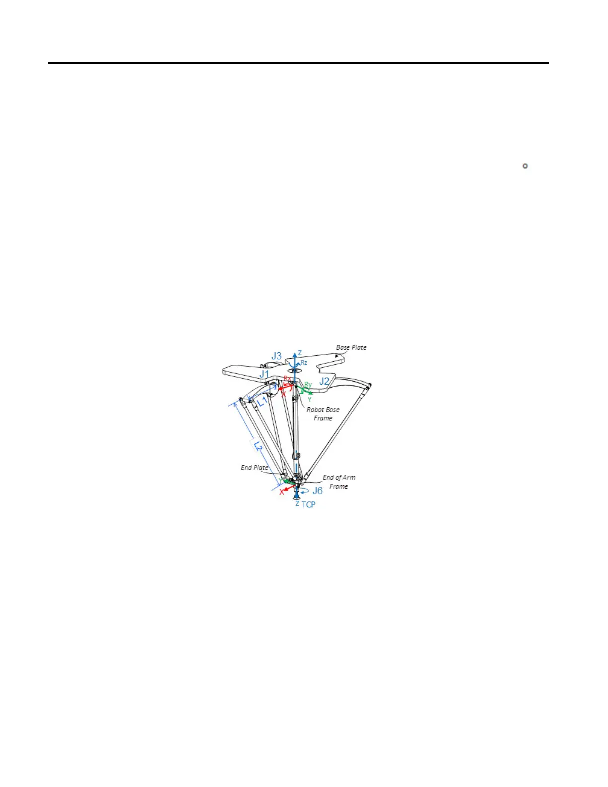
A four-axis Delta robot that moves in six-dimensional Cartesian (X, Y, Z, Rx, Ry,
Rz) space is often called a spider or umbrella robot. This illustration is an example
of a four-dimensional Delta robot.
In Logix Designer application, the four-degrees of freedom are configured as four
joint axes (J1, J2, J3, and J6) in the robots coordinate system. All joint axes are
either:
• Directly programmed in joint space.
• Automatically controlled by the embedded Kinematics software in the
application from instructions programmed in a virtual Cartesian coordinate
system.
This robot contains a fixed top plate (Base Plate) and a moving bottom plate (End
Plate). The fixed top plate is attached to the moving bottom plate by three
link-arm assemblies. All three of the link-arm assemblies have a top link arm (L1)
and bottom link arm (L2).
Configure a Delta J1J2J3J6
Coordinate System
 Loading...

