Geometries with no orientation support
76 Rockwell Automation Publication MOTION-UM002F-EN-P - February 2018
Work envelope for Articulated Dependent robot on page 78
Define configuration parameters for Articulated Dependent robot on page
79
The reference frame is the Cartesian (typically the source) coordinate frame that
defines the origin and the primary axes, X1, X2, and X3. These are used to
measure the real Cartesian positions.
Failure to properly establish the correct reference frame for the robot can cause the robotic arm to move to
unexpected positions causing machine damage and/or injury or death to personnel.
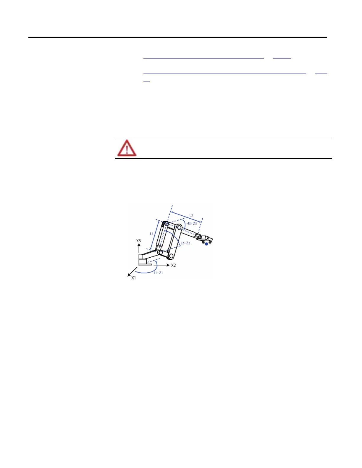
Example 1: Articulated Dependent robot 1
This diagram illustrates the reference frame for an Articulated Dependent robot at
the base of the robot.
These equations represent the Articulated Dependent robot joint positioning
shown in Articulated Dependent robot 1 diagram.
• +J1 is measured counterclockwise around the +X3 axis starting at an angle
of J1=0 when L1 and L2 are both in the X1-X2 plane.
• +J2 is measured counterclockwise starting with J2=0 when L1 is parallel to
X1-X2 plane.
• +J3 is measured counterclockwise with J3=0 when L2 is parallel to the
X1-X2 plane.
When the robot is in this position, the Logix Designer application Actual Position
tags for the axes must be:
• J1 = 0.
• J2 = 0.
• J3 = 0.
Reference frame for Articulated
Dependent robots
 Loading...

