Geometries with no orientation support
Rockwell Automation Publication MOTION-UM002F-EN-P - February 2018 77
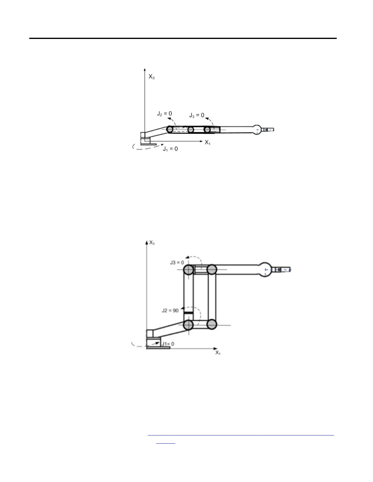
Example 2: Figure 79 - Articulated Dependent 2
When the robot is in this position, the Logix Designer application Actual Position
tags for the axes must be:
• J1 = 0.
• J2 = 90.
• J3 = -90.
Example 3: Articulated Dependent 3
If the position and joint angle values of the robot are unable to match the
Articulated Dependent 2 or in Articulated Dependent 3 examples, use a methods
outlined in the Method to Establish a Reference Frame for an articulated
dependent robot topic to establish the Joint-to-Cartesian reference frame
relationship.
See also
Methods to establish a reference frame for an articulated dependent robot
on page 78
 Loading...

