Geometries with orientation support
Rockwell Automation Publication MOTION-UM002F-EN-P - February 2018 147
Work frame offsets on page 137
Work frame examples on page 139
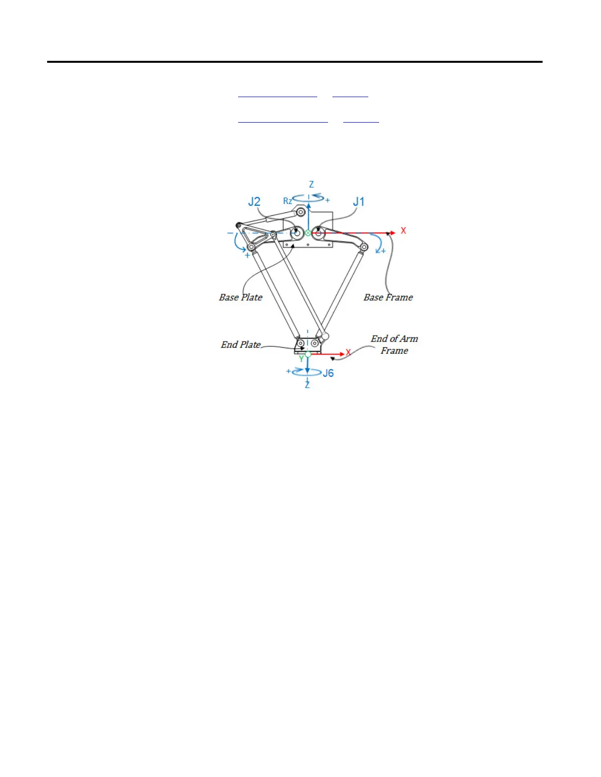
This illustration shows a three-axis Delta robot that moves in three-dimensional
Cartesian (X, Z, Rz) space.
In Logix Designer application, the three-degrees of freedom for this robot are
configured as Joint 1 (J1), Joint 2 (J2), and Joint 6 (J6) axes in the robot's
coordinate system.
The three joint axes are either:
• Directly programmed in joint space.
• Automatically controlled by the kinematics calculations when instructions
are executed in the application, programmed in a virtual Cartesian
coordinate system.
This robot contains a fixed top plate (Base Plate) and a moving bottom plate (End
Plate). The fixed top plate is attached to the moving bottom plate by two, two
link-arm assemblies (L1 and L2) which are identical in mechanical arm lengths.
Coordinate System
 Loading...

