Geometries with orientation support
146 Rockwell Automation Publication MOTION-UM002F-EN-P - February 2018
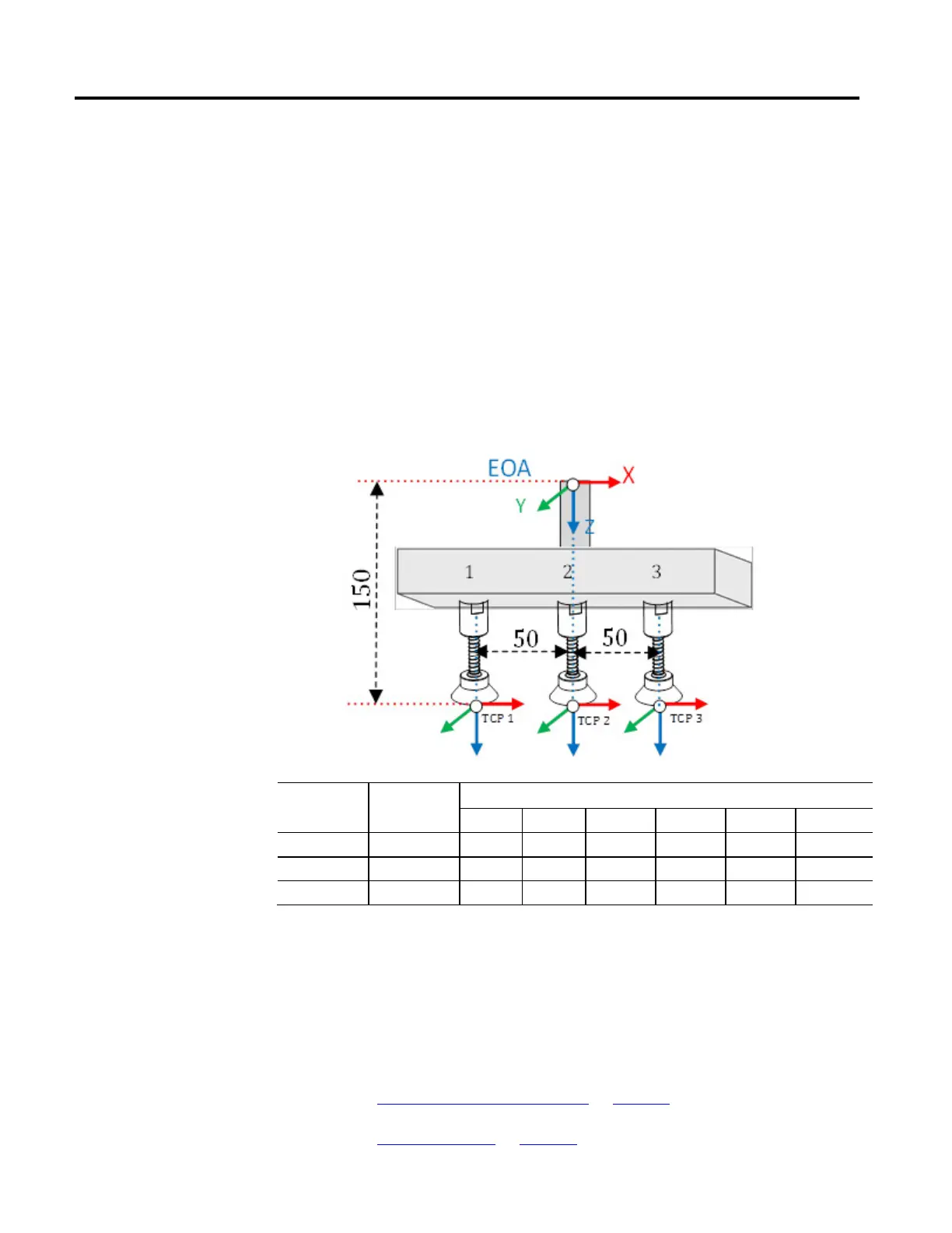
image. Individual tool frames are established through the tool frame offsets shown
in the table below.
In the application program, dynamically change the tool using the MCTO
instruction, while tracking the conveyor positions using the MAG or MAPC
instructions. Initiate the MCTO instruction with the first gripper’s tool frame
offset values. The robot picks the object using first gripper while the conveyor is
moving. When first move is completed, initiate new MCTO instruction with the
second gripper’s tool frame offsets. The robot picks another object using second
gripper.
Tip:
Refer to ToolChangeAllowedStatus status bit for dynamically changing the tool frame offsets. If this bit is
not set and new MCTO is initiated for tool change then new MCTO will generate #61 with extended error
#10. First the MCTO instruction bit (IP) is cleared when the second MCTO is initiated successfully.
Tool
Frames
Tool ID Tool Frame Offsets
X Y Z Rx Ry Rz
Tool 1 0 -50 0 150 0 0 0
Tool 2 1 0 0 150 0 0 0
Tool 3 2 50 0 150 0 0 0
Tip: To use this Kinematic sample projects, on the Help menu, click Vendor Sample Projects and then click the Motion
category.
The Rockwell Automation sample project's default location is:
c:\Users\Public\Public Documents\Studio 5000\Sample\ENU\v<current_release>\Rockwell Automation
See also
Define coordinate system frames on page 134
Tool frame offsets on page 142
 Loading...

