Geometries with orientation support
Rockwell Automation Publication MOTION-UM002F-EN-P - February 2018 181
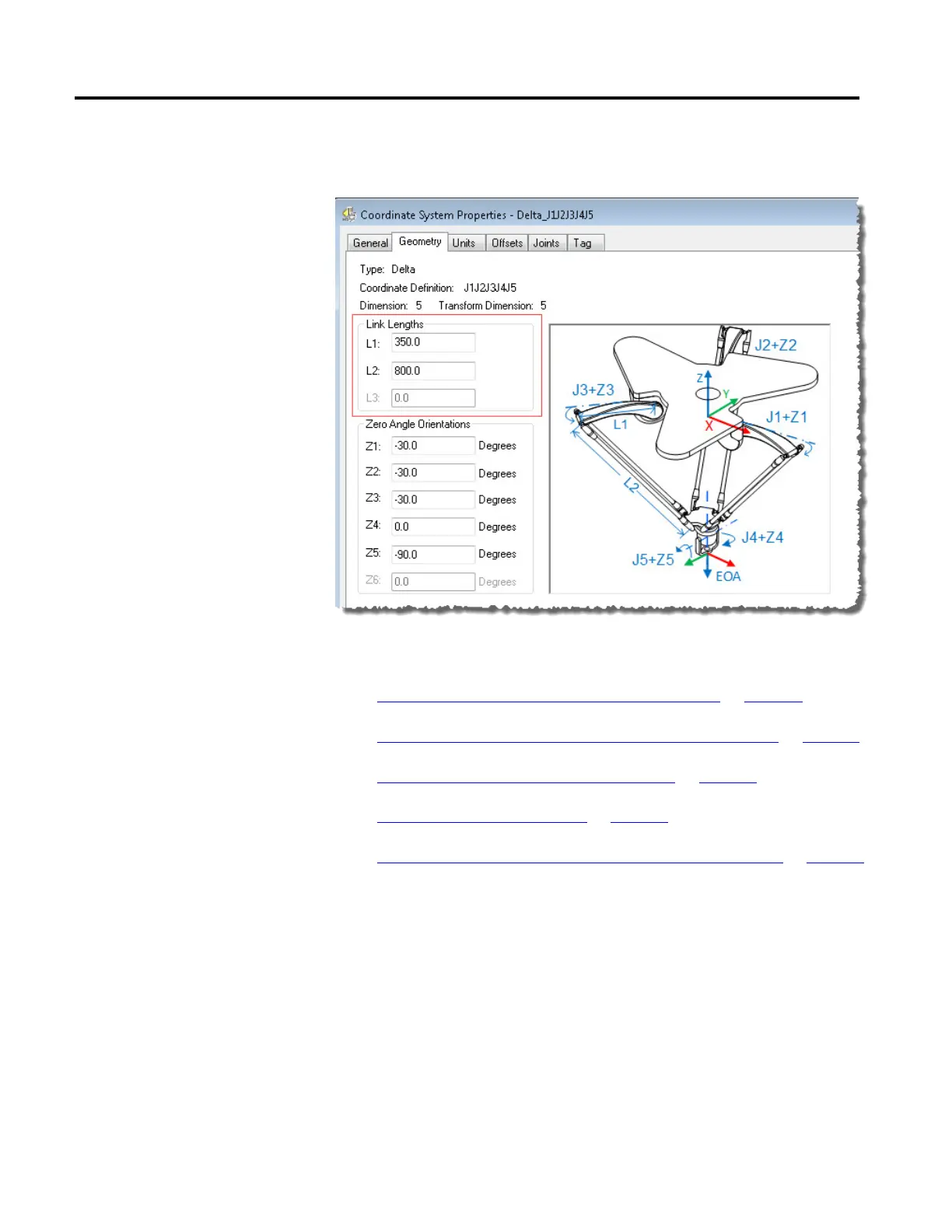
Enter the link lengths on the Geometry tab in the Coordinate System
Properties dialog box.
See also
Configuration parameters for Delta J1J2J3J4J5 robot on page 180
Base and Effector Plate dimensions for Delta J1J2J3J4J5 robot on page 181
Swing Arm Offsets for Delta J1J2J3J4J5 robot on page 182
Coupling between J4 and J5 axis on page 186
Configure Zero Angle Orientations for Delta J1J2J3J4J5 robot on page 188
In a 5-axis Delta robot configuration, Base and End plate offsets are represented as
Rb and Re offsets.
• Rb - This offset represents the Base plate offset value. Enter the value equal
to the distance from the origin of the robot coordinate system to one of the
actuator joints.
dimensions for Delta J1J2J3J4J5
robot
 Loading...

