Geometries with orientation support
144 Rockwell Automation Publication MOTION-UM002F-EN-P - February 2018
This table shows the current restrictions on the tool frame offsets for different
robot geometries supported by Logix Designer applications.
Geometry Type Coordinate
Definition
Tool Frame Offsets
X Y Z Rx Ry Rz
Delta
J1J2J6 Allowed Allowed Allowed Not Allowed Not Allowed Allowed
J1J2J3J6 Allowed Allowed Allowed Not Allowed Not Allowed Allowed
J1J2J3J4J5 Allowed Allowed Allowed Not Allowed Allowed Not Allowed
Tip:
The offset values must be set to 0
for restricted orientation offset inputs. The
MCTO/MCTPO instruction generates error #148 for invalid orientation offsets.
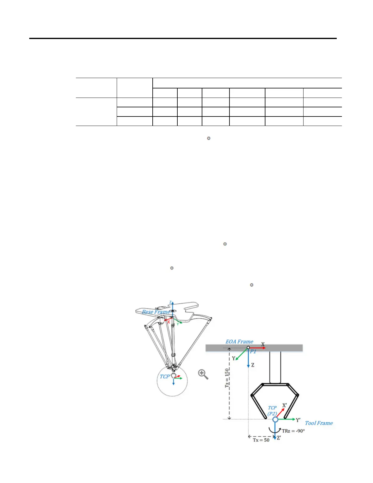
Establish a Tool frame
This diagram illustrates establishing a new Tool frame (X’Y’Z’) from the EOA
frame (XYZ) and change in the end position P of the robot with reference to a
new Tool Frame.
The simple gripper tool is attached at the end plate of 4 axis delta robot. TCP
point is measured from the EOA frame of the End plate. The Tool Frame X’Y’Z’
is located at 50 units on X axis, 150 units on Z axis, and rotated at -90 degree on Z
axis of the EOA frame XYZ. The Tool frame offset values are set as (X = 50, Y =
0, Z = 150, Rx = 0, Ry = 0, Rz = -90
)
Assume that the robot’s end position (P) is measured as P1 (X = 0, Y = 0, Z =
-800, Rx = 180
, Ry = 0, Rz = 0) from the base frame of the robot to the EOA
frame. With respect to a new tool frame, the end position (P) changes as P2 (X =
50, Y = 0, Z = -950, Rx = 180, Ry = 0, Rz = 90
).
 Loading...

