18 Rockwell Automation Publication IASIMP-QS035B-EN-P - April 2015
Chapter 1 Prepare the Kinetix 5500 Drive Hardware
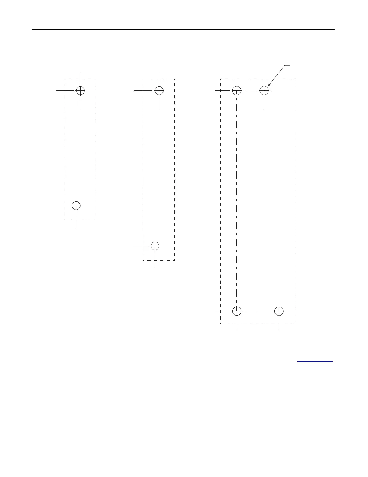
2. Drill the hole pattern for your frame 1, frame 2, or frame 3 standalone drive.
These hole patterns are only for standalone drive installations. If you have multiple drives to mount and would like to
u
se the zero-stack mounting feature, refer to the Kinetix 5500 Servo Drives User Manual, publication
2198-UM001,
for additional hole patterns and mounting information.
3. Attach your drive to the panel.
The recommended mounting hardware is M4 (#8-32) steel bolts. Observe bonding techniques as described in the
user
manual.
4. Tighten all mounting fasteners.
Apply 2.0 N•m (17.7 lb•in) maximum torque to each fastener.
0
0
243.84
(9.6)
5.00
(0.2)
193.68
(7.6)
0
0
4.51
(0.2)
272.0
(10.7)
0
52.50
(2.1)
0
34.00
(1.3)
8x
ØM4 (#8-32)
Frame 3
Standalone Drive
Frame 1
Standalone Drive
Frame 2
Standalone Drive
Dimensions are in mm (in.)
 Loading...


