Ladder Diagram (LD) elements Chapter 3
Rockwell Automation Publication 2080-RM001D-EN-E - February 2015 39
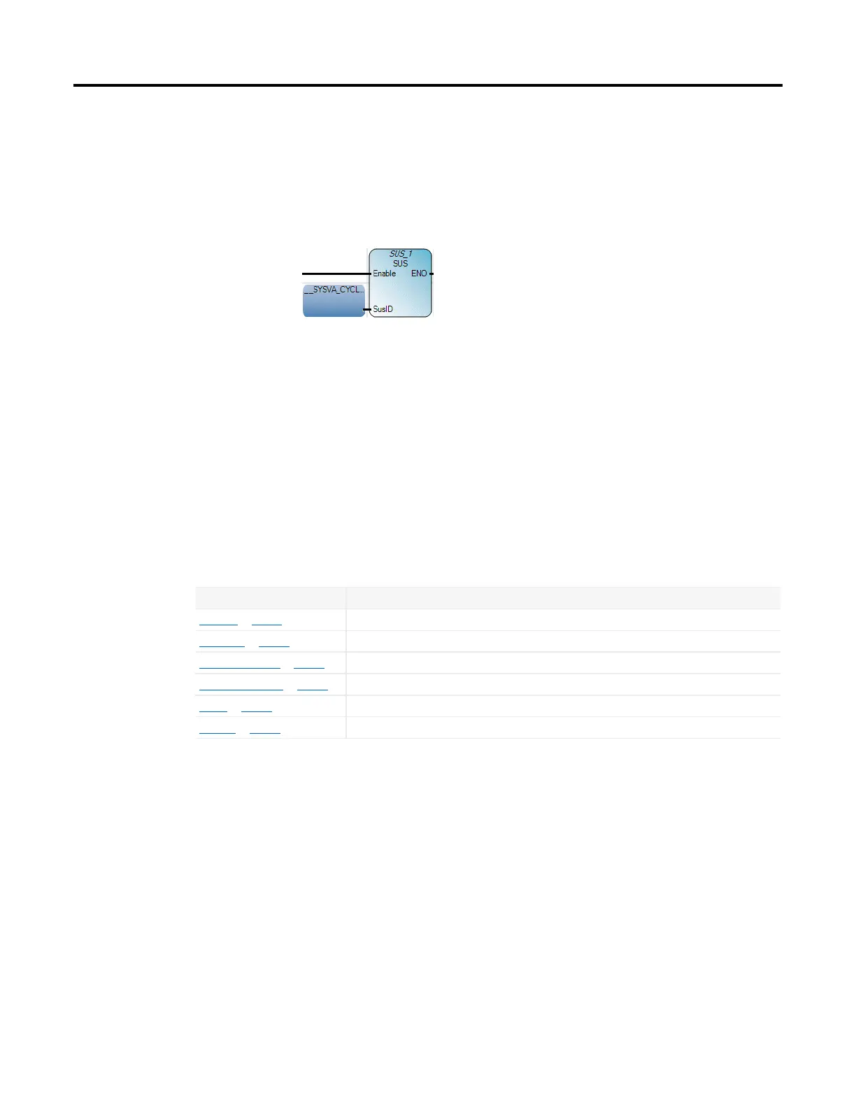
Example: Enable input
In some cases, Enable parameters are required for instruction blocks that execute
on call. The following example shows an SUS instruction block with an Enable
input.
Coil
Coils are graphic components of an LD diagram that represent the assignment of
an output or of an internal variable. In an LD diagram, a coil represents an action.
A coil must be connected on the left to a Boolean symbol, such as a contact, or to a
Boolean output of an instruction block. Consequently, coils can only be added to a
defined rung in the LD language editor. After a coil is added, its definition can be
modified.
You can add the following coil element types to your LD program from the
Toolbox.
Coil element Description
Direct coil on page 41 Direct coils support a Boolean output of a connection line Boolean state.
Reverse coil on page 41 Reverse coils support a Boolean output according to the Boolean negation of a connection line state.
Pulse rising edge coil on page 42 Pulse rising edge (or positive) coils support a Boolean output of a connection line Boolean state.
Pulse falling edge coil on page 42 Pulse falling edge (or negative) coils support a Boolean output of a connection line Boolean state.
Set coil on page 43 Set coils support a Boolean output of a connection line Boolean state.
Reset coil on page 44 Reset coils support a Boolean output of a connection line Boolean state.

 Loading...


