102 Rockwell Automation Publication 6000-UM002E-EN-P - April 2018
Chapter 5 Preventative Maintenance and Component Replacement
1. Remove the mounting bolts (M6 x 20) from both sides of the Power
Module.
2. Disconnect the Three-phase Input Power Cables.
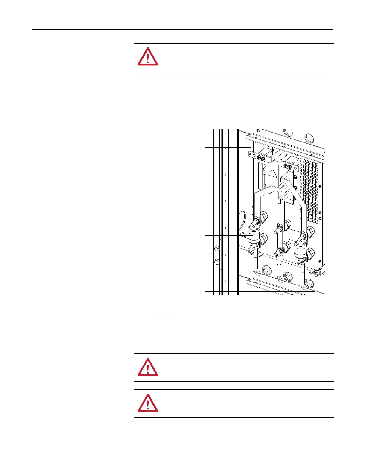
Figure 34 - Power Module Component Location
3. Remove the Output Copper Bars that connect adjacent Power Modules
(Figure 35
).
If the Power Module is at the end of a row, remove the VSB and Motor
cable instead of an output copper bus.
4. Disconnect the fiber optic cables.
ATTENTION: The high-voltage power source must be switched off before
replacing a Power Module. Wait for 20 minutes before opening the cabinet
doors. Verify that all circuits are voltage-free, using a hot stick or appropriate
high voltage-measuring device. Failure to do so may result in injury or death.
Fuse
Output copper bar (not shown)
connection location
Fiber optic cables connection point
Three-phase input cables
from isolation transformer
M6 x 20 mounting bolt
ATTENTION: When removing the fiber optic cables, be careful to prevent the
cables from straining or crimping as the resulting loss in light transmission will
impact performance.
ATTENTION: Minimum bend radius permitted for the fiber optic cables is 50
mm (2.0 in.). Any bends with a shorter inside radius can permanently damage
the fiber-optic cable.

 Loading...


