Rockwell Automation Publication 6000-UM002E-EN-P - April 2018 103
Preventative Maintenance and Component Replacement Chapter 5
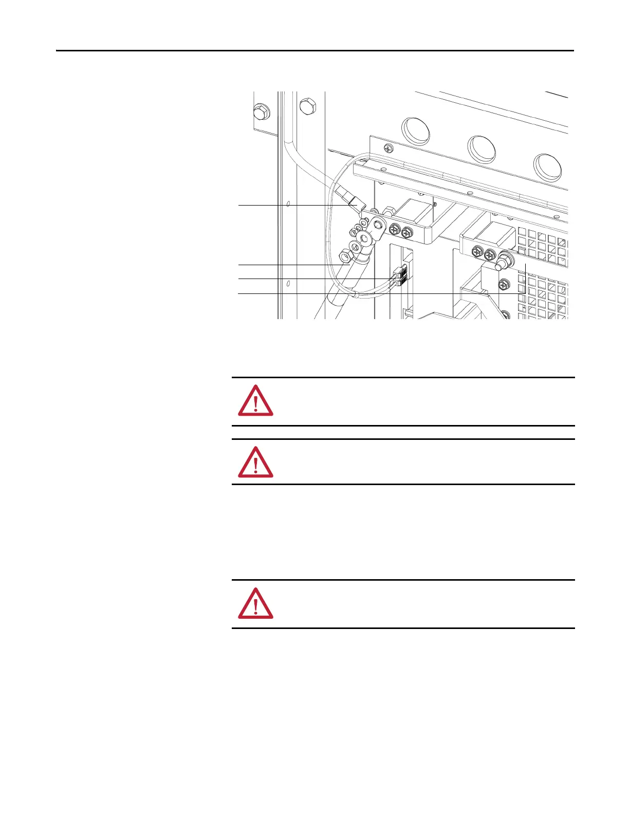
Figure 35 - Close up of Fiber Optic Location and Power Cables
5. Carefully withdraw the Power Module.
6. Install the new Power Module in reverse order of removal.
Using the Lift Cart
Power Modules rated above 350 A are shipped separately, therefore site
installation and cable connection is needed. In this case, a lift cart is supplied for
power cell replacement.
The lift cart’s hydraulic cylinder can be operated by either a hand or foot crank.
The lifting capacity is 400 kg (882 lb).
Motor cable
VSB cable
Output copper bar
Fiber optic cables
ATTENTION: Do not use the front mounted positioning handles for lifting the
Power Modules. They are designed to position or withdraw the Power Module
when on the tray assembly.
ATTENTION: The Power Module finger assemblies must be fully seated on the
cabinet stab assemblies.
ATTENTION: Only authorized personnel should operate the lift cart. Keep hands
and feet away from the lifting mechanism. Do not stand under the lift tray
when in use. Store the lift cart with the tray fully lowered.

 Loading...


