118 Rockwell Automation Publication 20Y-TG001C-EN-P - April 2017
Appendix D Disassembly/Assembly Diagrams and Spare Parts
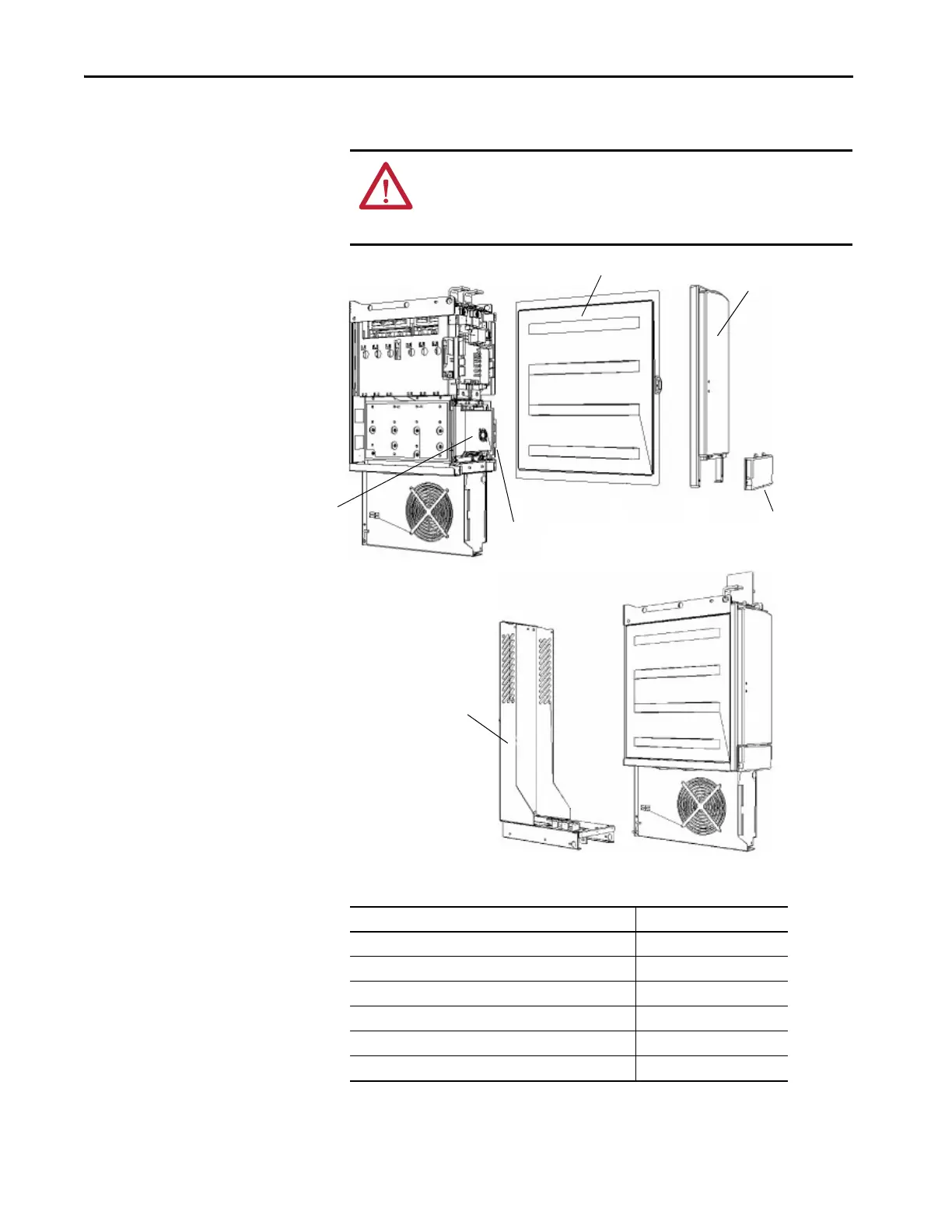
AFE Power Structure
Assembly
Figure 38 - AFE Power Structure Assembly External Components
ATTENTION: The sheet metal cover and mounting screws on the ASIC Board
that is located on the power structure are energized at (-) DC bus potential
high voltage. Risk of electrical shock, injury, or death exists if someone comes
into contact with the assembly.
Terminal Cover
Front Cover
Mounting
Rack
Side Cover
ASIC Assembly
Upgrade Kit
Fuse Holder for Fan
Inverter
Table 13 - AFE Power Structure Assembly External Component Part Numbers
Part Name Cat. No.
ASIC assembly upgrade kit (without ASIC Board) 20-FR10850
Bus bar assembly N/A
Fuse holder for fan inverter (only AC fan system) 20-PP20300
(1)
Fan inverter fuse (only AC fan system) 20-PP20202
(1)
Terminal cover N/A
Front cover N/A
 Loading...


